Live Stacking
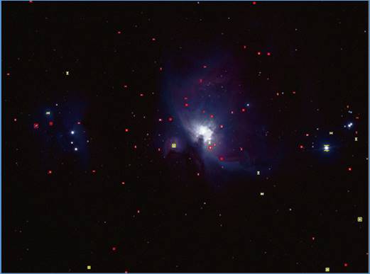
Live stacking is a feature that enables the capture of deep sky images within SharpCap without the traditional requirements of a high accuracy, guided, equatorial mount and long sub-frame exposures. The capture of a larger number of shorter exposures and software correction within SharpCap for any drift or rotation of the field of view between frames makes deep sky astrophotography accessible to a much wider audience at much lower cost.
The traditional requirements of long exposures and accurately guided mounts arise from traditional CCD cameras used for deep sky astrophotography have a high-level of read noise. If there is a high read noise every time that a frame is captured, long exposures are required to allow faint deep sky objects to be seen above the read noise level. Long exposures mean that an equatorial mount which tracks accurately and is typically auto-guided is required.
This all changes when modern low noise CMOS cameras are used instead of CCD cameras. The low level of read noise means that faint objects can be detected in far shorter exposures (and can be enhanced by stacking many short exposures – something that would not be possible without low read noise). If exposures are short enough (often 30s or less), mount accuracy is less important as the amount of drift during a 30s exposure is far smaller than the drift during a 300s exposure. Away from the zenith, field rotation due to the use of an ALT/AZ mount is also not usually going to be significant during a single 30s exposure. SharpCap corrects for any gradual drift or rotation between successive frames by tracking the movement of the brightest stars in the image. As the number of frames captured increases the noise level visible initially visible in the stacked image will reduce giving astounding deep sky images with the minimum of fuss.
Because of the simple satisfaction of watching deep sky images appear in real time without the need to use a separate stacking program, Live Stacking is particularly well suited to outreach uses.
Live Stacking is started by choosing the ‘Live Stack’ option from the Tools menu or by selecting the Live Stack toolbar button.
Once selected, Live Stacking will immediately begin capturing, aligning and stacking frames. A minimum of 3 stars must be detected in each frame for alignment to be possible (see the following sections for further details on alignment and how to customize star detection). It is possible to save the stacked image at any point using the Save button that appears in the Live Stack work area – the Save can be repeated as required – for instance after 50 frames and again after 100 frames and so on.
The Live Stacking User Interface
The UI to control Live Stacking appears in the work area below the camera image, and is divided into an always visible left panel and a series of tabs to the right.
The left panel controls and reports on the most important aspects of the stacking process and is always visible during Live Stack. The right panel has six tabs to allow the monitoring and control of the details of the Live Stack process.
Left Panel
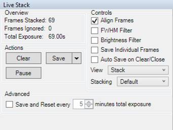
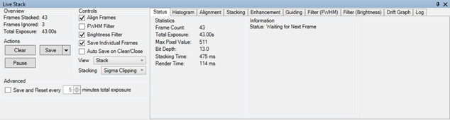
Overview Group
· Frames Stacked – the current number of frames on the stack.
· Frames Ignored – the number of frames ignored (not stacked). This can happen because of alignment problems, SharpCap not seeing enough stars, frame failing to achieve a focus score criteria or other reasons.
· Total Exposure – the length of time the current stack has been running. Some cameras cannot report their exposure value to SharpCap (for instance DirectShow Frame Grabbers). In those cases, SharpCap estimates the exposure based on the time between subsequent frames.
Controls Group
· Align Frames – turn alignment and de-rotation on/off (default on). See Alignment tab on right panel for more details.
· Enable FWHM Filter – enable/disable filtering of each frame by the average FWHM (focus quality) value. High FWHM value frames are discarded as indicating poor focus/seeing/transparency/cloud. See Filter tab.
· Brightness Filter – enable/disable filtering of each frame by the brightness of the stars detected in the frame. A reduction in star brightness is often caused by thin cloud.
· Save Individual Frames – when enabled save each frame as a separate file (FITS/PNG). Note, that only the stacked frames are saved. The individual frames will be found in a folder like YYYY-MM-DD\Capture\HH_MM_SS\rawframes.
· AutoSave – enable/disable saving the stack automatically when the clear button is pressed or another action causes the stack to be reset.
· View – you can choose to view either
o Stack (show the stack so far – the default)
o Individual Frames (show the individual frames being captured by the camera)
· Stacking – Allows you to choose the stacking algorithm between the default algorithm and the sigma-clipping algorithm. See <<<Stacking Tab>>> for more details. Note that changing the stacking algorithm will reset the stack.
The Clear button will reset the stack to start from scratch. Note, other actions can cause the stack to be reset; for instance, changing camera, resolution, colour space. Changes to exposure, gain, brightness or applying a dark/flat will not cause the stack to be reset.
The Save button has 4 sub options:
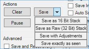
· Save as 16 Bit Stack will rescale the stacked data linearly between the 0 and the maximum pixel value into the range 0 to 65535 and save this as a 16-bit FITS file. The 16-bit FITS option is the default as it gives a high bit depth image with the full range of the image used (i.e. brightest pixel is 65535).
· Save as Raw (32-bit) Stack will save the full 32-bit stack data without any scaling as a 32-bit FITS file. The maximum value in it will depend on the number of frames stacked, meaning more adjustments will be needed when viewing (without further adjustment this FITS file will probably appear black when opened into a FITS viewing application).
· Save with Adjustments will save the image with the Live Stacking adjustments applied (i.e. after histogram adjustments and colour adjustments have been applied) as an 8 or 16-bit PNG file (depending on bit depth of camera being used).
· Save Exactly as Seen will save the image exactly as shown on screen as an 8-bit PNG file. This will include the effects of both the live stacking histogram and colour adjustments and the display stretch if one is applied.
The Pause/Resume button will temporarily stop or resume stacking. Stacking will automatically be paused if the Live Stack window is closed or if the user switches to another tool such as Histogram. Switching back to Live Stack will allow stacking to be resumed in these circumstances if another action would cause the stack to reset has not been carried out (for instance changing resolution or colour space).
Finally, in the Advanced section, you can choose to automatically save and reset the stack after a selectable interval. This can be useful if you live in an area with heavy aircraft traffic as taking a large number of shorter stacks may avoid a single set of aircraft lights spoiling a long stack.
Status Tab
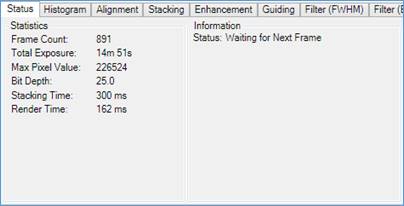
The Status tab shows some more detailed information about the stacking process and the stack so far. Of interest is the stacking time, which is the amount of time taken to process the alignment and stacking calculations needed for each frame. If this time is longer than the exposure length, frames will be dropped from the stack (due to the previous frame still being stacked when the next frame arrives). The Render Time indicates how long the calculations to redraw the image on screen take to complete. Certain Live Stacking features such as noise reduction and sharpening can increase the render time. If the render time is large then the program will only respond slowly to changes in the Live Stack histogram or colour settings.
The right-hand information panel shows the current status or warning or error messages if stacking errors are occurring.
Histogram Tab
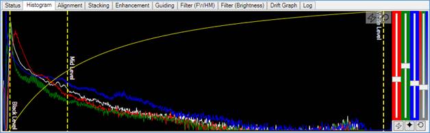
The Histogram tab shows not only the image histogram but allows the image levels to be stretched by moving the three vertical dashed yellow lines which represent the White Level, Black Level, and Mid-Level. The yellow curve shows the Transfer Curve which determines how bright the viewed image is for a given histogram level. For pixels at the Black Level point (and below) the viewed image will be black. For pixels at the Mid-Level point the viewed image will be mid (50%) grey. For pixels at (or above) the White Level point, the viewed image will be at maximum (100%) intensity.
· Tweaks to the Black Level, White Level and Mid-Level affect how the image is shown on screen and how it is saved if choosing Save with Adjustments or Save Exactly as Seen.
· The changes do not affect the actual values in the stack or the result if Saving As 16 or 32 bit stacks.
· Changes made to the levels here do not affect the shape or position of the histogram shown in the Live Stacking panel, but will show in the Mini Histogram in the Camera Control Panel on the right.
· Additionally, the Histogram Stretch Controls on the right, in the Camera Control Panel, affect only how the image is viewed on screen and do not affect saved data except when using the ‘Save Exactly as Seen’ option.
Adjust White Level
· The white level applies to the horizontal axis of the histogram, so left is 0% and right is 100%. It is not usually necessary to adjust this line.
Adjust Black Level
· The black level applies to the horizontal axis of the histogram, so left is 0% and right is 100%.
· Turn up the Black Level slightly (move slider to right) to suppress sky glow/chip noise and give a dark background to an image. Turning the black level up too far can give the image an unnatural look.
Adjust Mid-Level
· The mid-level line also applies to the horizontal axis of the histogram and specifies the level on the histogram that will be displayed as a mid (50%) grey level. The mid-level is restricted to be between the black level and the white level.
· Moving the mid-level control to the left towards will enhance the brightness of dim areas of the image. Moving the mid-level control to the right towards the white level will darken dim areas of the image but enhance contrast in the brighter areas of the image.
Transfer Curve
·
The yellow transfer curve shows how the levels between the black
and white points are going to be displayed on screen. The
shape of this line is determined by the positions of the black
level, white level and mid-level controls, and the line acts in a
way similar to the ‘Curves’ adjustment found in many image
processing applications. For this line the vertical axis of
the graph is the display brightness from black (bottom) to white
(top). The brightness of a pixel in the viewed image is
calculated by taking its horizontal position of the pixel on the
histogram, moving up to the red transfer curve line and taking the
vertical position of the line at that point as the displayed
brightness for that pixel.
Auto-Stretch and Reset Buttons
These buttons are located at the top-right of the main histogram area. The Auto-Stretch button (with the lightning bolt) will automatically set the black, mid and white levels to appropriate values to enhance the view of the image being stacked. The Reset button (with the circular arrow) will set the levels back to their default values. Note that the use of the Auto-Stretch button requires a SharpCap Pro license.
Colour Adjustment
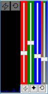
The colour adjustment sliders can be found to the right of the main histogram area and only show for colour cameras. The four sliders are, in order from left to right:
o Red Adjustment
o Green Adjustment
o Blue Adjustment
o Saturation Adjustment
The three colour sliders can be used to adjust the colour balance of the image. The saturation slider can be used to increase or decrease the amount of colour seen. Adjustments made here affect the image as viewed on screen and the saved images when choosing either ‘Save With Adjustments’ or ‘Save Exactly as Seen’.
The colour adjustment sliders can apply an adjustment of between -10db (0.32x) and +10db (3.2x) to each colour channel.
Below the colour sliders are three buttons – from left to right:
o Auto colour balance based on aligning image histogram peaks
o Auto colour balance based on star colours
o Colour adjustments reset button
Alignment Tab
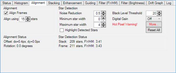
The Alignment tab controls the alignment process which, along with the FWHM filter, depends on the detection of stars in each image. SharpCap can only align images in which it can detect stars (do not use Live Stack for planetary or lunar images).
· A minimum of 3 stars is required for Live Stack with alignment to work. However, for reliability and good alignment a star count of 10-15 or more is to be preferred.
Alignment Group
· Align Frames – enable or disable the alignment of frames. The first frame in any stack becomes the reference frame – all other frames are aligned with that frame when alignment is enabled. SharpCap uses the stars it detected in the first frame to align all subsequent frames with the stack. Stars in the stack are re-detected if any of the star detection parameters are changed. The absolute minimum requirement is 3 stars detected, although having 3 stars is no guarantee of alignment working if too close together or close to being in a straight line for instance. Ideally, aim for 10-20 or more stars detected with a good distribution across the frame.
· Align using – to select number of stars. It can be 10, 15, 20 or 25 stars. Using a larger number of stars may slow down the stacking process, but may give better alignment results. Only increase this value if detecting plenty of stars but still having difficulty aligning.
Star Detection Group
· Reduce Noise – when enabled applies a Gaussian blur to help SharpCap to ignore low level noise and hot pixels. Selecting Reduce Noise is recommended.
· Black Level Threshold – anything under this level is treated as black and can help to ignore low level noise. The default is 50, the range 1..254 in steps of 2 by pressing the up/down arrows. Any value required (in the range) can be typed directly into the box.
· Digital Gain – can be used to apply a gain during the star detection process if stars are faint and are not being detected. Values can be Off, 2x, 4x, 8x. Enabling this may help if SharpCap is not detecting enough stars.
· Minimum star width – increase this to help stop hot pixels being detected as stars. The default is 2, range 2..32 in steps of 2 by pressing the up/down arrows. Any value required (in the range) can be typed directly into the box.
· Maximum star width – reduce this to limit detection of very bright bloated stars. The default is 16, range 4..32 in steps of 2 by pressing the up/down arrows. Any value required (in the range) can be typed directly into the box.
·
Highlight
Detected Stars – checking this will put boxes around
the detected stars – yellow stars are used for alignment, red are
not used for alignment. This can be very helpful to determine
and understand the causes of problems with star detection and
alignment.
· Hot Pixel Warning – this shows when the combination of settings chosen for star detection combine to allow a single hot pixel to be detected as a star. If your camera tends to produce large numbers of hot pixels then this can be a problem as the hot pixels detected as stars may prevent correct alignment. You can prevent hot pixels being detected as stars by
o Increasing the Noise Reduction setting
o Increasing the Minimum Star Width Setting
o Reducing or turning off the Digital Gain Setting
· Reset All – this button resets all star detection related options to their default values.
Status Groups
· Shows various data including offset of the frame from the stack, rotation and number of stars detected.
Stacking Tab
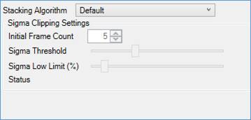
The Stacking tab allows the selection of either the Default or Sigma Clipped stacking algorithm and also allows adjustments to be made to the settings for the Sigma Clipped algorithm.
Default Stacking
The Default Stacking Algorithm adds the pixel values from each frame to the stack data. All frame date from stacked frames is included in the stack. The default stacking algorithm does not have any adjustable controls.
Sigma Clipped Stacking
The Sigma Clipped Stacking Algorithm averages stacked frames together to create the stack data. The algorithm tracks fractional pixel values, so stack quality is maintained. The algorithm also compares the value of each pixel in a new frame to the value of that pixel so far in the stack – if the two differ too much the data from that pixel is ignored for that frame.
The advantage of Sigma Clipped stacking is that anomalous features in individual frames – for example satellite or aeroplane trails do not end up in the stack data, since the anomalously bright pixels are rejected by the algorithm.
SharpCap keeps track of the mean value of each pixel in the stack as well as the amount of variability in the pixel value for each pixel. The amount of variability for each pixel is known as the standard deviation or Sigma value for each pixel.
The decision on whether to include the data for a particular pixel from a particular frame in the stack is made on the basis of the difference between the pixel value in the frame and the mean pixel value in the stack so far for that pixel. The size of this difference is compared to the sigma value for that pixel multiplied by the Sigma Threshold value. If the difference is larger then the pixel data is ignored.
The following controls are available to adjust the behaviour of the Sigma Clipped Algorithm:
· Initial Frame Count – this controls the number of initial frames during which the algorithm learns what values are expected for each pixel without rejecting any potentially unusual values. A value in the range 5 to 10 is usually sufficient.
· Sigma Threshold – this controls how different from the current stack pixel value a frame pixel value must be to be rejected. Setting a higher value here will mean that less pixel data is discarded but will reduce the effectiveness of the algorithm at excluding anomalous pixel data. This control should be adjusted while watching the Status information which shows the fraction of pixels being rejected in each frame.
· Sigma Low Limit (%) – this control specifies a lower limit on the value of sigma calculated for any pixel in the stack. This is required to prevent incorrect rejection of image data when the individual frames have very little noise.
Note that Sigma Clipped Stacking requires a SharpCap Pro license.
Enhancement Tab
The controls in the Enhancement tab provide a way to improve the live stack image by either reducing the noise in the image, sharpening the image or both. All tools in the enhancement tab, except for the simple Gaussian Blur noise reduction require a SharpCap Pro license.
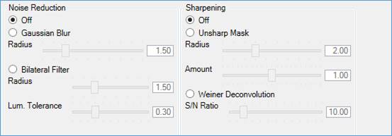
Gaussian Blur is a simple noise reduction tool which blurs each pixel in the image with its neighbours. This helps reduce the noise in the image but also has the effect of blurring the image somewhat. The Radius control determines how large an area each pixel is blurred over, increasing this value will strengthen the noise reduction effect but also blur the image more.
Bilateral Filter is a more sophisticated noise reduction tool which can reduce noise in areas of similar colour without blurring detail as much as the Gaussian Blur noise reduction tool. Once again, the Radius control determines the area over which the noise reduction operates. The Luminance Tolerance control determines how big a change in brightness is required to be regarded as a feature that will be preserved. The Bilateral Filter algorithm requires much more calculation than the Gaussian Blur algorithm and may slow down live stacking when using high resolution cameras or on slower computers.
Unsharp Mask is a simple image sharpening tool which strengthens the sharper components of the image relative to the less sharp components, producing a sharper looking image. The Radius control adjusts the split between the ‘sharp’ and ‘less sharp’ components of the image – the higher the value set the larger the scales of details that will be considered part of the ‘sharp’ component. The Amount control determines how much boosting is applied to the ‘sharp’ components of the image. Applying the Unsharp Mask sharpening unfortunately has the side effect of increasing image noise in the image. Setting the Amount control to too high a value may lead to an unnatural look to the image.
Weiner Deconvolution is a sophisticated image sharpening tool based on determining the shape of stars in the stacked image as an indication of the nature of blurring in the stacked image, then attempting to undo this blurring to the image to produce a sharpened image. The only control to adjust for this sharpening algorithm is the Signal to Noise Ratio. This is an estimate of how much brighter the image signal is in the stack than the noise. The Signal to Noise Ratio control should be set to the highest value that gives a natural look to the image (setting the value too high will give the image an unnatural, ‘orange peel’ look). The Weiner Deconvolution algorithm requires a significant amount of calculation and may slow down live stacking when using high resolution cameras or on slower computers.
The sharpening and noise reduction algorithms affect both the image as shown on screen and the image saved when using Save with Adjustments or Save Exactly as Seen. Since the sharpening and noise reduction is applied every time the image on screen is updated, using these tools may reduce the responsiveness of the live stacking to changes in other controls such as colour adjustment or histogram changes.
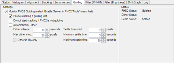
Guiding Tab
SharpCap can work with the popular freeware guiding application PHD2 to monitor and control guiding and dithering while live stacking.
In order to enable integration between SharpCap and PHD2, ensure the following:
· PHD2 is a recent version and running on the same computer as SharpCap
· the Enable Server menu item must be selected in PHD2
· the Monitor PHD2 Guiding checkbox must be checked.
If SharpCap has successfully connected to PHD2 then a status such as ‘Guiding’, ‘Calibrating’ or ‘Stopped’ will be shown in the Status box on the right. If PHD2 monitoring is disabled or SharpCap cannot connect to PHD2 then ‘Not connected to PHD2’ will be shown.
Monitoring Guiding
Basic guiding monitoring is managed by the two options:
Pause stacking if guiding lost – if enabled then SharpCap will pause any live stack in progress if the PHD2 status changes from ‘Guiding’ to any other status. Note that with this option set you can still start stacking with PHD2 not guiding (or not connected). Also note that if you manually resume the paused stack, SharpCap will not re-pause it unless PHD2 again changes from the ‘Guiding’ to non-guiding state.
Do not start stacking if PHD2 is not guiding – if enabled then SharpCap will pause any new stack that is started if PHD2 is not in the ‘Guiding’ state (or is not running or not connected).
Notification messages will be shown in the SharpCap notification bar when PHD2 guiding starts or stops.
Dithering
SharpCap Pro users can also enable dithering using PHD2 while live stacking. In order to enable dithering, tick the Automatically Dither checkbox and set the options to choose dithering parameters.
SharpCap will send instructions to PHD2 to dither at regular intervals. If the dither time arrives while a frame is being captured, SharpCap will wait until the frame ends before starting dithering. During the dither operation, SharpCap will pause the live stack so that frames that may be blurred due to the dithering movement are not included in the stack. The stack will be resumed after the end of the first frame to finish after the dither has finished settling.
Dither Interval – this is the minimum time that SharpCap will wait between the end of one dither starting the next dither. As noted above, dither operations are delayed until the end of any frame in progress. The Dither Interval should be set to a time considerably longer than the camera exposure time, otherwise an unacceptably high fraction of frames will be lost due to dithering.
Max Dither Step – this specifies the maximum distance that any dither movement can be, measured in guide camera pixels (i.e. pixels in PHD2, not in SharpCap)
Settle Threshold – when the movement between two guide camera frames drops below this number of pixels then the dither is considered to have ‘settled’ – i.e. the mount movement is complete and images taken should no longer be blurred by movement.
Minimum Settle Time – a dither will not be considered to be settled until this amount of time has elapsed after the end of the movement, even if the Settle Threshold is met before this time has elapsed.
Maximum Settle Time – a dither will always be considered to be settled after this amount of time has elapsed, even if the settle threshold has not been met.
Dither in RA only – restrict dithering to the Right Ascension axis only.
See the PHD2 Documentation for more information on dithering using PHD2.
Filter (FWHM) Tab
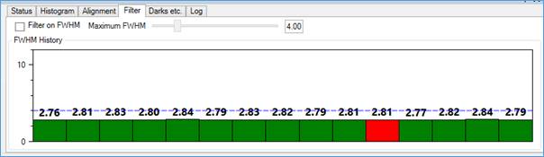
This filter allows poor-quality frames (poor atmospheric conditions or clouds) to be excluded from the stack. Frame quality is judged only by the FWHM (full-width-half-maximum) estimate of the quality of focus in the frame.
· Filter on FWHM – check to enable FWHM (focus score) filtering.
· Maximum FWHM – use the slider to specify a maximum FWHM value for frames to be used. It shows a history of recent frames. Used frames are green, frames discarded by filtering are red.
· Filtering does not apply to the first frame in any stack.
Filter (Brightness) Tab
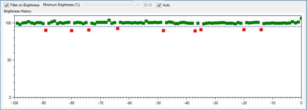
This filter can help detect reductions in frame brightness caused by passing cloud, stopping frames spoilt by cloud from being added to the stack. The frame brightness is judged based on the brightness of stars detected in the frame, so this filter can only operate correctly when sufficient stars are detected in the frame.
The graph shows the brightness of recent frames with the most recent frames on the right-hand side and the oldest frames on the left. Frames that are rejected are shown as red squares, frames that are stacked are shown as green squares.
The controls available are:
· Filter on Brightness – check to enable brightness filtering
· Minimum Brightness – adjust the level of brightness below which frames will be rejected. The level is measured relative to the average brightness of recently stacked frames.
· Auto – check this box to allow SharpCap to set the Minimum Brightness threshold automatically based on the statistics of recent frames. Uncheck this box to allow the Minimum Brightness to be set manually.
Drift Graph Tab
The drift graphs show the history of movement and rotation of the image during the current live stack.
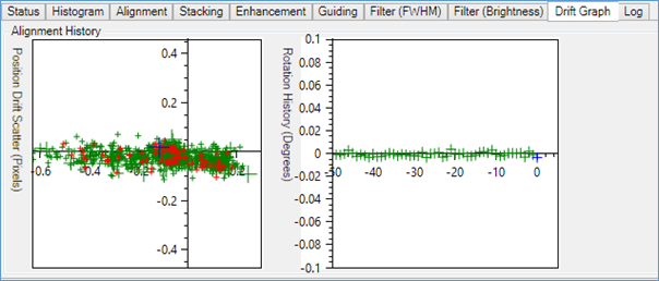
The left-hand graph shows the amount of movement of the image on a scatter (X,Y) graph. Green crosses represent frames that were added to the stack, red crosses represent frames that were not added to the stack for some reason (filtering, stacking paused, etc). More recent frames have larger crosses and the most recent frame is a blue cross.
The right-hand graph shows the history of rotation of the stack with the amount of rotation measured on the vertical axis and time (with the most recent frames on the right) measured on the horizontal axis. Rotation will be very low for equatorial mounts, but may be significant for Alt-Az mounts.
Hovering the mouse over either graph will display a larger version.
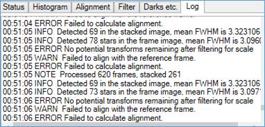
Log Tab
Shows some log information of Live Stacking in more detail than is saved in the main SharpCap log. If something is not working, this is the place to look.
Live Stack Reference
In the background, SharpCap maintains a 32-bit integer value for each pixel of the stack with the value from each frame being added to the pixel value.
· For a 16-bit camera it is possible to stack up to 32768 (215) frames before running out of values in the stack.
· For an 8-bit camera it is possible to stack up to 16 million frames (224) before running out of values in the stack.
All files saved during a stack will be saved in a single folder (raw frames and processed stack images saved in subfolders). This helps keep the saves from the stack together. The folder is named after normal file naming rules based on the time stacking was started and the name of the target object selected.
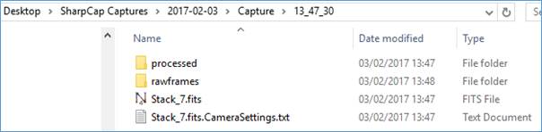
If the name of the target in the toolbar is changed during Live Stacking, SharpCap will rename the output folder.
Using Live Stacking
A useful video demonstration of using the Live Stack function in SharpCap can be found, courtesy of Charles Copeland, at https://www.youtube.com/watch?v=zIlJHyVWei4 .
Although the video shows SharpCap 2.7, it is still valid for SharpCap 2.9 and beyond. This is a good demonstration of what can be achieved with video stacking software using a NexStar 6SE telescope, analogue video camera and 0.5x focal reducer. Be aware of the comment “if using v2.9 be sure to set Digital Gain to 2X in the Alignment tab” on the web page, below the video. This may be helpful if it is difficult to detect enough stars, however turning on the Digital Gain when it is not required will reduce alignment accuracy slightly.
The video is worth watching again and again ……