Feature Tracking
Feature tracking is a tool designed to assist with solar/lunar/planetary imaging, where it can help stop the target from drifting out of view even if the telescope is not tracking perfectly. Guiding during longer exposure deep sky imaging can be achieved using tools such as PHD2 guiding.
Hardware Requirements
In order to use Feature Tracking, you need to be using either
· An ASCOM compatible GOTO mount – the mount must be selected in the Hardware Tab of the SharpCap settings and connected.
Or
· A supported camera with an ST4 pulse guiding port that is connected to a pulse guide-capable mount. Select ‘On Camera ST4’ as the mount option in the Hardware Tab to use this option.
Either of these will allow SharpCap to move the mount in all four directions, although the ST4 option only allows a single movement rate, so the ASCOM option should be preferred if available.
There is no need to have a separate guide scope or guide camera for this functionality. SharpCap will use images from the main imaging camera to track any movement without affecting normal imaging functionality.
Setting up Feature Tracking
Feature Tracking is launched by selecting it from the Tools menu, which will show the Feature Tracking Window. This is a separate window meaning that Feature Tracking can be used at the same time as other features such as Focus Assistance, Seeing Monitor orHistogram.
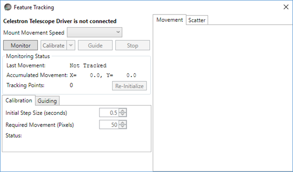
The top left of the Feature Tracking Window shows the hardware that will be used for guiding and allows the mount movement speed to be chosen if an ASCOM GOTO mount is being used. If appropriate guiding hardware is not selected, or not connected, a warning will be shown here and guiding functions will be unavailable.
Starting Monitoring Image Drift
Press the Monitor button to begin monitoring the image for drift. SharpCap will automatically find a range of identifiable feature points on the image and highlight them on-screen with small circles. As the image moves, these points will follow the feature on the image, allowing SharpCap to track how far the image has moved and in what direction.
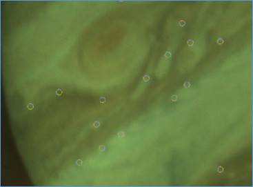
If the image is very low contrast or very out-of-focus then SharpCap may not be able to find sufficient image features to track accurately.
Tracking may be lost if
· The image moves very rapidly
· The image moves such a long way that most of the tracked features move out of view
· The image brightness is increased or decreased drastically
When image monitoring is active, the Monitoring Status area will be updated regularly.
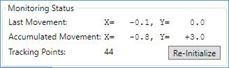
The Last Movement values show how far the image has moved between the most recent frame measured and the previous measured frame. The Accumulated Movement shows the total amount of image movement detected since monitoring was started. These measurements are in pixels.
The Tracking Points value shows how many features on the image SharpCap is currently tracking. If the number of tracked features falls then the Re-Initialize button can be used to find a new set of features to track while monitoring is still active.
You may wish to test if the tracking is working correctly by moving your mount slightly – this should be detected and lead to changes in the Accumulated Movement figures.
Calibration
SharpCap needs to work out which direction (and how far) the image moves when the mount is moved in the four different directions (RA +/-, Dec +/- or Alt +/-, Az +/-). This is affected by a wide range of factors such as camera orientation, telescope focal length, optical configuration of telescope, reducers or Barlow lenses being used, etc. In order to avoid having to enter all of the above information (which would be tedious and prone to error), SharpCap works out this information by moving the mount in each direction and measuring how the image moves – this process is known as Calibration.
One image monitoring is running successfully with a suitable number of tracking points, press the Calibration button to begin the calibration process.
During the calibration process, SharpCap will move the mount in each of the four directions, starting with small movements and gradually increasing the size until the image shift is detected. SharpCap will continue moving the mount until a total image shift of 50 pixels is measured (this value can be configured in the calibration settings). During the calibration process for each direction, a graph showing the measured image movement on the Y axis against the total mount movement on the X axis is drawn.
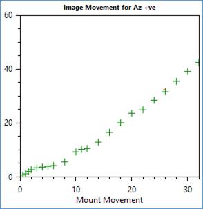
The graph should generally be a straight line, although as shown here it is common for the image not to move as much for the initial mount movements – this is due to backlash in the mount mechanism and should not normally cause a problem unless the amount of backlash is excessive.
During the four phases of the calibration process, a graph will build up in the Scatter tab showing how the image moved in response to each of the four mount movement directions. This graph should form the shape of an ‘X’ or cross. The two arms should be roughly straight, and close to being at right angles with each other.
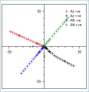
If the scatter plot does not resemble the one shown above then the calibration process may fail. Possible causes of calibration failure include:
· The image does not move in response to SharpCap moving the mount in one of the four directions
· The image moves at significantly different rates when the mount is moved in opposite directions
· When moving the mount in opposite directions the image does not move in opposite directions
· The direction the image moves when the mount is moved in the RA (or Az) axis is not roughly at right-angles to the direction the image moves when the mount is moved in Dec (or Alt)
The most likely cause of all of the above is excessive backlash in the mount movements. It may help to select a higher movement rate (if possible) to reduce the influence of backlash. Setting a higher Initial Step Size or Required Movement value may also help. The reason for any calibration failure will be shown in the Status area of the Calibration controls and more information may be available in the SharpCap guiding log, which can be found in the same folder as the normal SharpCap log files.
Once calibration has completed successfully, the Guide button will become enabled.
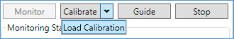
Note: After a successful calibration, SharpCap saves the calibration results so that they can be re-used later. If you return to Feature Tracking after re-starting SharpCap, you can choose to load the saved calibration by using the dropdown at the right-hand side of the Calibrate button.
The saved calibration will only be valid if you have not adjusted or rotated the camera and are still imaging in the same region of sky.
Guiding in Action
After calibrating or loading a previously saved calibration, press the Guide button to begin guiding. SharpCap will then attempt to move your mount so as to keep the target roughly stationary in image. Note that SharpCap does not attempt to keep the target stationary to ‘pixel perfect’ levels – just to keep it from slowly drifting out of view.
The status of the guiding process can be monitored by checking the Accumulated Movement information, which should stay close to X=0 and Y=0 when guiding as active and also by viewing the Movement Graph, which shows both the history of image movement and corrections made
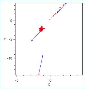
Red crosses on the Movement Graph represent measurements of the image position relative to the target position (the X and Y axes are measured in pixels). The most recent measurements are shown as larger red crosses while older measurements are smaller. Blue arrows represent guiding corrections made to bring the image back to the target position.
There are three adjustments that can be made to control the guiding procedure:
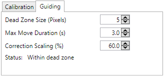
· Dead Zone Size – this is the size of the zone (in pixels) around the target position in which no guiding corrections at all will be made. The default is 5 pixels.
· Max Move Duration – the maximum length of a move command that will be issued (in seconds) as part of a guiding correction. The actual amount moved will depend on both this and the guiding rate chosen.
· Correction Scaling – the percentage of the calculated correction to apply when issuing a guiding command. Typically setting this between 50 and 70% ensures that there are no problems with over-correction or oscillation from one side of the target to the other, even if the calibration data is not 100% accurate.