Polar Alignment
SharpCapPolar Alignment is designed to help astronomers achieve excellent polar alignment quickly, easily and reliably. The idea was inspired by the PhotoPolarAlign application created by Themos Tsikas. Themos has been kind enough to help with testing and suggestions during the development of the polar alignment feature in SharpCap.
The Polar Alignment procedure can be started from the Tools menu.
How does it Work?
The polar alignment works by analysing two pictures taken of the area near the pole. Take one picture, let SharpCap analyse it, rotate the mount by about 90 degrees about the RA axis and take the second picture. By recognizing the stars in each of the pictures, SharpCap can work out two things:
1. The exact area of sky represented in each image - this process is called Plate Solving. SharpCap has a built-in plate solving algorithm that doesn't need an internet connection or any other program or database to be installed. SharpCap's plate solving only works within 6-7 degrees of the pole though (N or S).
2. The centre of rotation about which the stars seem to rotate when going from the first to the second image.
Since SharpCap has worked out exactly what RA & Dec the telescope was pointing at in each image, it knows where in the image (or perhaps how far off the image) the celestial pole is. SharpCap also knows the point about which the stars seem to rotate - that's where the mount’s RA axis is currently pointing. If those two points are the same, the polar alignment is perfect. If they are not the same, all that is required is to adjust the Altitude and Azimuth adjusters of the mount until they are the same point and that will complete polar alignment.
SharpCap will guide through this process with on-screen instructions, including a live update of how far is still needed to move the mount in each direction to get perfect alignment.
What is required?
· An equatorial mount.
· A camera supported by SharpCap combined with a telescope/finder-scope on the mount.
· A field of view in the camera of between about 0.5 degrees and about 2.5 degrees.
· A clear view of the celestial pole.
· Able to see at least 15 stars in the field of view.
· To already be aligned within about 5 degrees of the pole
It is not required to have perfectly aligned the guider scope or main scope as the polar alignment process is not affected by this sort of misalignment.
SharpCap cannot align if you do not have a clear view of the celestial pole through at least a 30-45 degree rotation in RA.
Step-By-Step
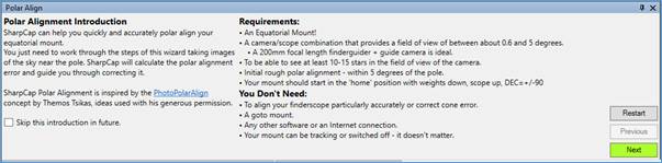
Introduction Stage
When first selecting the Polar Alignment tool you will see an introduction which reminds you of the requirements to get polar alignment working. Once you have checked that you have everything you need, you can move on by pressing the green Next button.
Once you have pressed Next, SharpCap will move on to capturing the first image.
First Image Stage
At this stage, SharpCap will try to plate solve each frame coming from the camera, beginning the Polar Alignment process.
This is a good time to make adjustment to your camera settings to ensure enough stars are visible. A good starting point is setting the exposure to 2 seconds and setting a relatively high gain (the exact value depends on the camera, but start in the upper half of the range).
If enough stars are detected and the field-of-view is the right size and close enough to the pole something like this should be seen:
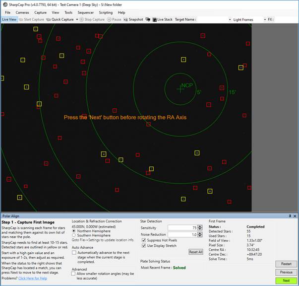
The stars SharpCap is using to perform the plate solving are highlighted in yellow, other stars are highlighted in red. The North (or South) celestial pole is shown and circles of different radii are shown around it. Note that the pole may be out of view - don't worry if it is, carry on to the next stage.
[Note: the ‘Next’ button will turn green when SharpCap is ready to advance to the next stage and that the user needs to press the button.]
If the plate solving fails and the Next button does not become enabled, there are three likely causes:
1. Not enough stars detected.
2. Too far from pole.
3. Field of view too large or too small.
The last two require physical changes to be made to the setup, but the first might be fixable by adjusting the star detection parameters at the bottom of the screen or by adjusting the exposure or gain of the camera in use. If the stars are too faint, try turning up the exposure, gain or star detection sensitivity. You could also try using the histogram stretch functionality to increase the brightness of the stars, as this will help SharpCap’s star detection.
Once the first frame is solved, press the NEXT button to move to the next stage.
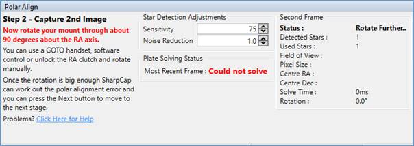
Second Image Stage
After pressing NEXT, rotate the RA axis through about 90 degrees. Do this either by unlocking the RA clutch or by using the mount's GOTO system if it has one.
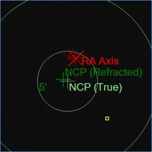
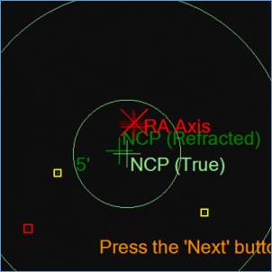
SharpCap will continue attempting to plate solve each frame - once it manages to solve a frame that has rotated far enough it will offer the option to move on to the adjustment phase - looking a bit like this:
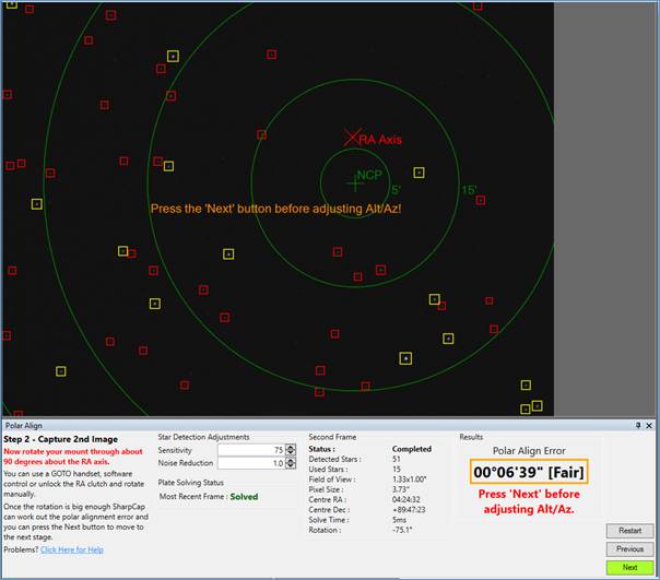
At this point, SharpCap has calculated the position in the image that the RA axis is pointing at - this is the point around which the image appeared to rotate and is marked with the red cross and RA label. The RA axis point might be out of view, so don't worry if it doesn't show up, so long as the Next button becomes enabled.
If the Next button is not enabled, try different amounts of rotation (or rotating in the opposite direction). If that still fails, it is likely that not enough stars are being picked up in the rotated position - the best way to fix this is to leave the mount in the rotated position and press the 'Restart' button to go back to the start of the alignment process. This leaves a view of the rotated position with the star detection controls available to adjust until a plate solve can be achieved in that orientation.
DO NOT ADJUST THE ALTITUDE OR AZIMUTH UNTIL NEXT HAS PRESSED TO MOVE TO THE FINAL STAGE.
Adjustment Stage
Once the button is pressed to move to the adjustment stage, one of the brighter stars on screen will be highlighted with an arrow pointing to a target, like this:
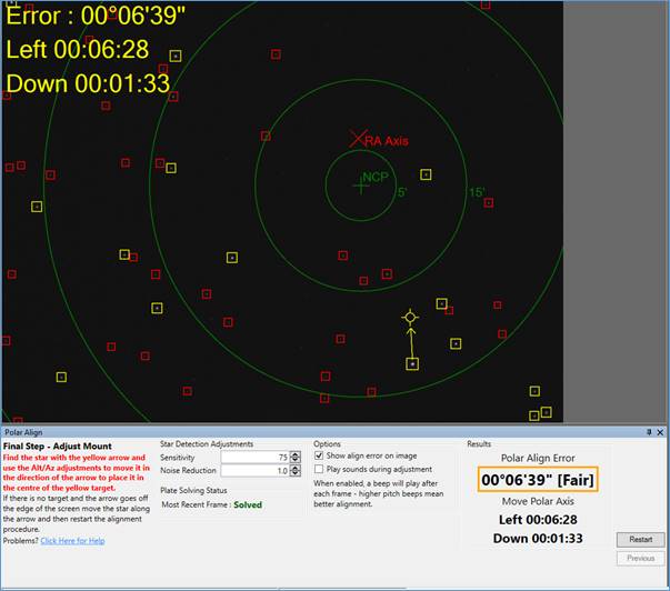
All that is required to get good polar alignment is to move the indicated star into the target - doing this will also line up the NCP with the RA axis and polar alignment done. At the bottom of the screen, below the Polar Align Error figure are some guidelines indicating which direction the mount needs to be moved. These are also repeated in large text overlaid on the camera image.
The movement directions should be interpreted as follows:
· Stand looking past your telescope and mount towards the celestial pole.
· The you should move the mount so as to shift the far end of the telescope (the one pointing at the sky) in the direction indicated
· That is, if the directions suggest left and down then (in the northern hemisphere) you should move the mount so the scope points further towards the west (left as you look past it towards the pole) and further down towards the horizon.
The direction suggestions are calculated based on your latitude and longitude – if you have not entered these accurately then the information on which direction to move (up/down/left/right) is only approximate.
During the adjustment phase the highlighted star might switch to a different one - no need to worry, just keep adjusting. As this gets closer the arrow and target changes to a pair of parallel lines that need to be brought together to finalise the alignment process.
If it is found that the length of the arrow isn't updating, or is only updating now and then, it is likely that the plate solving isn't working for every frame - either ignore the problem and just get the star into the target or alternatively try further tweaks to the gain, exposure or star detection sensitivity to get the star detection and plate solving working more reliably. Watch the Most Recent Frame status indication – for good results that should almost always show Solved in green – if it frequently changes to Could not solve then you need to check your star detection or camera settings.
An alignment error of under 2 minutes of arc is considered good and under 1 minute of arc is excellent. Do not waste time trying to get the alignment error all the way down to zero.
Tips
· Try using a guiding camera (such as ZWO120MC, QHY5LII, Altair GPCAM and others) with a ~200mm focal length finder-guider - this will give the correct field of view.
· Read the on-screen instructions - they will walk through the procedure.
· Select a high gain and an exposure of 2-4s - this should let SharpCap see enough stars.
· If the mount is on a pier, the pier mounting plate bolts can often give finer adjustment than the mounts own alt/azimuth adjusters.
· Don't worry if the scope or finder is aligned with the mount correctly - misalignment won't affect the result.
· SharpCap needs to know the approximate longitude to work out which direction (up/down/left/right) the mount needs to be moved. If the time zone is set incorrectly, the wrong directions may be suggested.
Configuring Polar Alignment
There are several options that can be used to configure the polar alignment process:
Skip this introduction in future
![]()
On the introduction page, checking this option will mean that the next time you run Polar Alignment, you will not see the introduction and will go straight to the First Image Stage.
Location & Refraction Correction
SharpCap can use your location for two aspects of the polar alignment process:
· Determining which direction is up/down/left/right when providing adjustment guidance
· Correcting for atmospheric refraction when aligning
By default, SharpCap will estimate your longitude from your computer time zone (for instance EST is estimated at 75W). SharpCap will prompt for Northern/Southern hemisphere in the First Image Stage and assume a latitude of either 45N or 45S
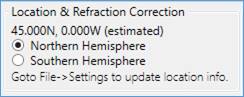
These default estimates of location are sufficient for the up/down/left/right guidance directions to work with a good degree of accuracy, but do not allow refraction correction to be enabled.
To enable refraction correction, you must go to the Polar Alignment tab of the SharpCap Settings and enter your exact location either directly or by setting SharpCap to retrieve location from your ASCOM mount. This will update the Polar Alignment tool to show your true location and the amount of refraction correction being applied.
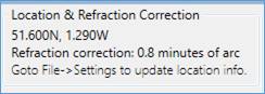
Note that it is probably not worth correcting for refraction if you are at a latitude of 40 degrees or more. The refraction of the polar becomes larger at lower latitudes, so correction becomes more important if you observe nearer to the equator.
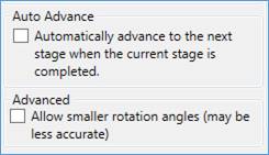
Auto Advance and Low Rotation Mode
Two other options that you may wish to enable are:
Auto Advance - enabling this option causes SharpCap to automatically move to the next stage when it becomes available – no need to press the Next button.
Allow smaller rotation angles – enabling this allows you to align with a smaller rotation between the two images. This may be useful for mounts with limited rotation such as sky trackers, but may be less accurate.
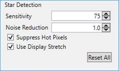
Star Detection Settings
These settings affect the detection of stars by the polar alignment process. Ideally, having about 30 to 50 stars detected in each image (of which 15 will be used) will give best results.
Sensitivity – This controls the overall sensitivity of the star detection process – increase this value to try to detect more stars, decrease it to reduce the number of stars being detected. Note the following:
· Setting a higher sensitivity can make star detection take longer, potentially slowing down the stacking process
· SharpCap will auto-adjust the sensitivity for you, turning it down (to a minimum of 75) if more than 200 stars are detected and turning it up (to a maximum of 75) if less than 15 stars are detected.
Noise Reduction – when enabled applies a Gaussian blur to help SharpCap to ignore low level noise and hot pixels. Increasing this may help detect stars correctly in noisy images and may help reduce problems with the polar error jumping to a different value with each new frame from the camera.
Suppress Hot Pixels – Enabling this option adjusts the star detection process to avoid detecting a star from a single hot pixel in the image. You may need to turn this off if you are using a large pixel camera and a short focal length telescope (i.e. your stars are very small).
Use Display Stretch – when this option is selected, any display stretch applied to the image is also used for star detection to help detect faint stars. In general, leave this option selected.
Adjustment Options
These options are available on the adjustment stage and are designed to help in situations where the computer running SharpCap is not easily visible while you are making physical adjustments to the mount altitude and azimuth.
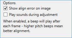
Show align error on image – this option places the alignment error and movement direction info on the camera image in a large, clear font. This information is visible and readable from a greater distance than the normal adjustment text below the image.
Play sounds during adjustment – when enabled, SharpCap will play a beep through the computer’s sound system as each adjustment frame from the camera is processed. As the polar alignment error is reduced, the pitch of the beep will increase, giving audio feedback on the alignment process.
Troubleshooting Polar Alignment
The information below should help you resolve a number of commonly encountered problems with the polar alignment tool.
No matter how much I adjust I can’t get the error down to zero!
STOP!!! You don’t need to get the polar align error down to exactly zero and you are wasting clear sky time if you try! A polar alignment within 1 arc minute of the pole is usually considered to be excellent and good enough for long exposure imaging.
Stuck at the first Step? The ‘Next’ button never becomes enabled?
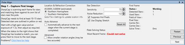
Getting stuck at this stage means that SharpCap can’t plate solve the view from the camera and work out where near the pole the camera is pointing. The most recent frame status will be ‘Could Not Solve’ in red all the time and the First Frame Status will be ‘Working’. Sometimes you will find that you will eventually get past this stage if a frame from the camera happens to be a bit better than the others and plate solves – don’t be tempted to move on if that happens as you will get stuck further on – fix the problem by running through the troubleshooting steps below instead.
The likely causes for this problem are:
Not enough stars being detected
if the number of detected stars is low (less than 10) then this is the most likely cause. Here are some suggestions to fix the problem
· Increase camera exposure up to 2-4s
· Increase camera gain if the camera has a gain control. Start at about 1/2 gain and work up towards maximum
· Increase the star detection sensitivity from the default value of 75
· Try using the Display Stretch functionality to increase the brightness of any stars – this will help the star detection work correctly.
· Check that your focus is correct – out of focus stars are harder to detect than in-focus stars.
The camera/telescope is pointed more than 5-6 degrees away from the pole
If plenty of stars are being detected, but the plate solving still fails, you could be starting from too far away from the pole
SharpCap has a star database out to 7 degrees away from the pole. If the image is taken of an area further from the pole than this then plate solving will fail. If you have a plate solving application installed and configured in SharpCap, you can use the Plate Solve (Solve Only) menu item to check exactly where the telescope is pointing. You can also make this check without a plate solving application by saving a frame (press the ‘Snapshot’ button) and uploading it to nova.astrometry.net for plate solving.
Hot pixels are being detected as stars
Some cameras suffer from hot pixels (pixels which have maximum value even though no light falls on them). With some star detection settings, single hot pixels may be detected as stars. If enough of these hot pixels exist and are detected, they may confuse the plate solving algorithm. If you are seeing this problem, ensure that the Suppress Hot Pixels option is checked and if necessary increase the Noise Reduction setting.
The field of view is too small or too large
SharpCap’s star database goes down to magnitude 13, meaning that it has over 16000 stars in each hemisphere available for plate solving calculations.
If your field of view is very small, there may be very few stars of magnitude 13 or greater within view of the camera, meaning that plate solving may fail. This happens more frequently as the field of view drops below 0.5° in either direction. If your field of view is only just smaller than this you may find that plate solving works intermittently – sometimes there will be enough stars in view for it to work and on other occasions you will by chance end up in a much less rich part of the sky and plate solving will fail.
If your field of view is very large, bright stars outside the area covered by SharpCap’s star database may be detected and confuse the plate solving operation. You could try using your camera in ROI (region of interest) mode to reduce the field of view.
Stuck in Step 2 or Step 3, nothing updates or everything takes a very long time
Once you have made adjustments to your telescope or moved SharpCap on to a new step in the polar alignment process, you shouldn’t have a long wait to see the results or for SharpCap to find a solution – a few seconds or so is typical. If you find yourself waiting more than 15 seconds then something isn’t right and the most common cause is that SharpCap is not able to plate solve every frame that is coming from the camera – in fact it might only be solving one frame in 10 or even one in 100.
This problem is easy to spot because the ‘Most Recent Frame’ status will be ‘Could not solve’ in red most of the time, but will change to a green ‘Solved’ every now and then.
This problem has exactly the same causes as the problem of being stuck at step 1 above. Use the suggestions found above under Not enough stars being detected to ensure that plenty of stars are detected and that all frames are being solved.
Note that sometimes you find this problem occurs for Step 2 even though you had a good solution straight away for Step 1 – this could be because the rotation around the RA axis has moved the camera to point to an area of sky that is harder to plate solve (perhaps fewer bright stars). A good trick for this problem is to leave the RA axis rotated but reset the SharpCap Polar Align routine back to Step 1 – then adjust the camera settings and star detection settings to get good plate solve in the rotated position before continuing the process by rotating back to the home position.
I get the wrong results – SharpCap says my Polar Alignment is great after adjustment, but it isn’t!
The first thing to check is that you have pressed the ‘Next’ button to move to the adjustment stage before you started tweaking the Alt/Az of your mount. If you don’t move to the adjustment stage then you will get incorrect polar alignment.
The most common cause of poor results is that something is shifting as the mount is being rotated around the RA axis. If you are using a guide scope/camera it could be that the scope is not mounted firmly or that a cable is pulling (or just hanging loose) which can shift the camera slightly. This problem has also been experienced by people who have a problem with their RA axis bearings!
The first thing to do if you suspect this problem is to confirm you have an issue. Run a SharpCap polar align normally (starting in the home position and rotating 90 degrees), and adjust as usual. Once you are finished, leave the scope at the 90 degree position and re-run polar alignment in SharpCap (this time rotating back to the home position when prompted to rotate). If the measurement from the second PA run matches the first then you probably don’t have this issue. If it doesn’t match by a big margin then flexure/movement as you rotate is the likely cause.
You can test for this problem quite easily by rotating the mount in stages of about 15 degrees. SharpCap plots a dark red cross at the point it calculates to be the centre of rotation (where the RA axis is pointing) for each stage of the rotation – these should form a tight group on screen if there is no flexure. In the screenshots below I deliberately let the cable to the guide camera hang loose for the polar alignment run shown on the left. Here you can see that the measured RA axis positions have drifted as I have rotated further due to the weight of the cable pulling on the camera. Once the cable was properly secured the RA axis positions form a much tighter group.
Loose Cable – note that the red vertical crosses are spread in a line away from the red diagonal cross (the final result).
Secured Cable – note that the red vertical crosses are in a tight group around the red diagonal cross.
If you discover that you have problems with flexure when rotating you can obviously try the usual hardware fixes of tightening all connections and securing all cables. Another possible trick that can help is to run the two steps of the polar alignment at about 30-40 degrees left of home and 30-40 degrees right of the home position. Depending on how your equipment is configured there may be less flexure when using this approach because the scope is largely ‘up’ during the hole procedure rather than going from ‘up’ to ‘sideways’ after rotation.
The directions that SharpCap says I should move my mount are wrong
Remember that the directions given are assuming that you are looking at your mount and you are facing in the direction of the pole (i.e. the telescope is pointing away from you at the pole). An instruction to move up means ‘move the mount altitude so that the objective end of the telescope is pointing higher up’, while right means ‘move the mount azimuth so that the objective end of the telescope points further to the right (east for NH. west for SH)’.
I can only just see Polaris over a house/tree/obstacle
If your view of the pole is limited, you may find that you can see the region around the pole when the mount is in the home position (scope up, weights down), but not when you have rotated through 90 degrees. In this case, try starting with the telescope 30-40 degrees to the left of the vertical and rotating it to 30-40 degrees the other side of the vertical (a total rotation of 60-80 degrees). This will keep the scope higher, hopefully maintaining view of the pole while still achieving the rotation required.