Getting Information from the Image
SharpCap gives you several ways to extract information from the image that can be used for purposes ranging from variable and double star measurements to collimation of telescopes to drift alignment to many more.
Reticules
SharpCap allows a range of reticule overlays to be placed on top of the image. The reticules can be adjusted (moved, resized, rotated) and put to use for many different purposes.
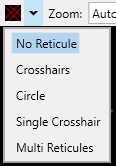
To show a reticule, select one from the reticules dropdown on the toolbar. You can also cycle through them by pressing the reticule button repeatedly (without opening the dropdown).
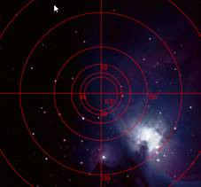
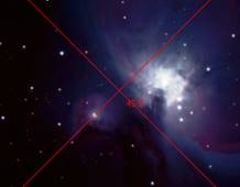
The reticules are generally displayed in red over the image – for example the circle reticule shown below.
The reticule can be adjusted in the following ways:
· The reticule can be ‘grabbed’ by the mouse and moved around in the display area.
· When the reticule is displayed, the center point can be moved by clicking anywhere on the preview display.
· Dragging or clicking with the right mouse button instead will adjust the orientation or size of the reticule.
The rotation angle of each reticule is also shown near the center of the reticule. For the circle reticule, numbers are displayed near each circle which indicate the radius of that circle, in pixels.
Note that selecting Pixel Value Readout or Pixel Position/Click to Recenter will disable any currently selected reticule. Selecting a reticule will disable these two tools if they are currently selected.
No Reticule
The reticule graphic is cleared from the image. This is the default.
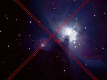
Crosshairs
A crosshair graphic is imposed over the image in the display area. This can be used to facilitate accurate mount alignment using a camera rather than an eyepiece.
Circle
A circular graphic is imposed over the image in the display area. This can be used to facilitate accurate mount alignment using a camera rather than an eyepiece. The rings can also be used to assist with collimation.
Single Crosshair
A simple single crosshair (one line only in each direction).
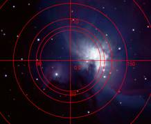
Multi Reticules
The multi-reticule tool allows up to 8 reticules to be placed on the image at once, which can be moved and sized independently. Six circular reticules and two line reticules are available. A separate window is shown to help choose which reticules to show and which one is currently being adjusted.
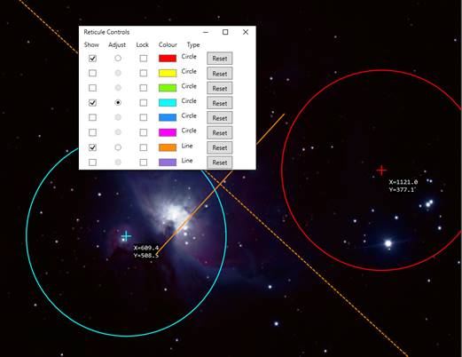
For each of the reticules, you can choose to show or hide it by ticking or unticking the checkbox in the Show column. You can also select one of the reticules to adjust by selecting the appropriate radio button in the Adjust column. The reticules can be locked to protect them from accidental adjustment.
The state of the multi-reticule tool is remembered automatically between uses, allowing for instance the reticules to be set up for a collimation camera once rather than needing to be adjusted each time. Each reticule can however be reset to defaults using the Reset button.
Note that line reticules show both the line itself and its perpendicular bisector. Circle reticules show additional larger and smaller concentric circles when being adjusted to make it easier to fit them to a circular feature in the image.
Pixel Value Readout
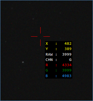
The Pixel Value Readout tool allows you to view the detailed brightness information about any pixel in the image. When you select the tool, a red crosshair will appear over the image along with information about the brightness of the pixel in the centre of crosshair.
You can click anywhere in the image to move the crosshair to that location. The crosshair will also follow your mouse location if you move the mouse around over the image with the left button pressed down. If you find it hard to place the crosshair exactly over the pixel that you require, you can use the zoom functionality available in the toolbar to zoom in on the area of interest, making the pixels larger and easier to select.
The information presented adjacent to the crosshair depends on whether a colour or monochrome camera is in use.
For a monochrome camera, the information is as follows:
· X – the X co-ordinate within the camera image that is at the centre of the crosshair.
· Y – the Y co-ordinate within the camera image that is at the centre of the crosshair.
· LUM – the luminosity (brightness) value of the pixel at the centre of the crosshair.
For a colour camera in RAW mode, the X and Y positions are shown along with
· RAW – the RAW brightness of the pixel
· CHN – the colour channel corresponding to the pixel – this could be R(ed), G(reen) or B(lue)
· R, G, B – the brightness values in the three colour channels for that pixel after debayering the image to full colour.
For a colour camera in RGB mode, the X and Y positions are shown along with
· R, G, B – the brightness values in the three colour channels for that pixel after debayering the image to full colour.
The pixel values will either be measured on a 0 to 255 range (for 8 bit modes) or a 0 to 65535 range (for 10, 12, 14 or 16 bit modes).
You can disable the Pixel Value Readout tool by selecting it again from the Tools menu.
Note that the values displayed will be affected by:
· Any active processing controls in the Preprocessing group – for instance dark subtraction, flat correction, background subtraction, etc.
· Any active display effects selected in the FX dropdown in the toolbar.
· Adjustments made to the image by live stacking (the readout will be the output of live stacking, not the input image).
Disable these features before using Pixel Value Readout if you wish to see the raw pixel values from the camera. The use of the Display Stretch in the mini histogram does not affect the values shown.
Note that selecting this tool will disable any reticule that is currently visible and conversely, selecting a reticule will disable this tool.
Stellar Photometry Estimation (Experimental)
The Stellar Photometry tool provides quick estimates of the brightness of stars in the images being captured by your camera. Various information is available, some of which requires Sensor Analysis data to be available for the camera being used or requires Plate Solving information.
Note that Stellar Photometry Estimation is a SharpCap Pro feature.
Typical results of the tool are shown below.
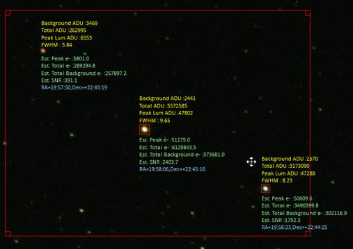
Stars are detected using the same procedures that SharpCap uses for focusing or live stacking, but in this case the information about the brightness of each star is collected and displayed. Information that can be shown for each star is as follows (note that the following refers to ADU – Analogue to Digital Units – which is basically the pixel value for a given pixel that comes from the camera with no processing):
· Background ADU – an estimation of the image background brightness in the vicinity of the star. This level might be caused by light pollution, nebulosity, the offset value of the camera, etc.
· Total ADU – the total brightness of the star (added across all pixels in the star image), measured from the Background ADU level.
· Peak Luminosity ADU – the ADU of the brightest pixel in the star image. This indicates whether the star is close to saturation or not.
· FWHM – SharpCap’s estimation of the Full-Width Half-Maximum size of the star. Note that for stars close to saturation, no value will be given (the value shows as NaN – ‘Not a Number’).
· Estimated Peak e- – the estimated number of electrons from the star in the brightest pixel (this corresponds to the Peak Luminosity ADU value). All electron based values require Sensor Analysis data for the camera to be available.
· Estimated Total e- – the estimated total number of electrons from the star captured across all pixels making up the star in the image.
· Estimated Total Background e- – the estimated total number of electrons corresponding to the image background level across the star area.
· Estimated SNR (Signal to Noise Ration) – this is an estimate of how much the brightness estimation of the star should vary due to statistical fluctuations in the number of photons collected in each image. This is calculated as
![]()
The numerator being the number of electrons coming from the star (signal) and the denominator is the estimate of the shot noise in the total number of electrons (star and background combined) collected over the area of the star.
· RA/Dec Co-ordinates – the J2000 co-ordinates of the star’s centre point are shown if plate solving data is available.
Various adjustments are available to control the star detection and the data shown on screen.
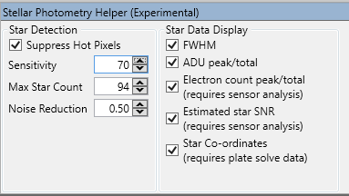
The most significant control is the star detection Sensitivity which can be used to control the number of stars being detected (higher sensitivity values will include fainter stars). The Maximum Star Count setting can also be used to limit the number of stars being detected if too much information is shown. It is also possible to use the Selection Area tool, which allows the star detection and annotation to be restricted to only applying to stars within the currently active selection area.
Important Note : Controls in the Preprocessing group, such as Subtract Dark, Apply Flat, Background Subtraction should not be used when this tool is being used, as they may cause incorrect values to be calculated, particularly for the electron based measurements.