ADC Alignment
Atmospheric Dispersion Background
In the same way that light rays entering or leaving a pool of water are bent at the surface, making things in the water appear less deep than they really are, light from the stars and planets is bent slightly as it enters our atmosphere from the vacuum of space. The light is bent very slightly towards the vertical, making the source appear a little higher in the sky (further above the horizon) than it would if there were no atmosphere. Not only that, but blue light is bent more than green light, which in turn is bent more than red light. The effect becomes stronger (both in terms of the total amount of bending and the amount it varies from red to blue) as the source gets closer to the horizon.
The effects of this can be seen in images as colour fringing on each side of bright objects, with blue fringes above the object and red below. An extreme example is shown below in an image of Venus in crescent form taken close to the horizon.
![]()
This effect leads to degradation of image quality, particularly when performing high resolution planetary imaging. Although it is possible to use software to undo some of the damage by re-aligning the red, green and blue colour channels, this approach cannot fix the problem that each colour channel is itself blurred by the effect – deep blue colours are bent more than those nearer the green end of the blue channel for instance.
A better solution to the problem is to use a device called an Atmospheric Dispersion Corrector (ADC), which is placed between the camera and the telescope. This device typically uses a pair of adjustable prisms to also apply a colour-dependent bending to the light. With correct adjustment, the effect of the ADC can be made to cancel out the effect of the atmosphere, removing (or at least greatly reducing) the damage done to the image quality. You can read more about ADCs and how they work on this excellent web page : Sky Inspector ADC Page.
The SharpCap ADC Alignment tool
SharpCap’s ADC alignment tool is designed to help you adjust your ADC to give optimal image quality. It provides an easy-to-see readout of how badly the three colour channels of the camera image are mis-aligned, thereby helping guide you through the ADC adjustment process.
Applying the tool to the highly dispersed image of Venus shown above, gives a result like this :
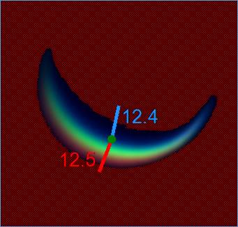
From this, notice the following :
· The background is shaded red – this is achieved by adjusting the Black Threshold control in the ADC Alignment panel (shown below). The red shaded area is ignored by SharpCap in its calculations, and you should adjust the Black Threshold so that all the dark area around the target is shaded, but avoid the shading covering any part of the target (including the colour fringes on its edges).
· The green dot shows the centre of brightness of the green channel of the image.
· The blue and red lines show how far (and in what direction) the centre of brightness of the blue and red channels are offset from the centre of the green channel. The length of the lines are increased to make them easier to see.
· The numbers adjacent to the lines show the size of the offset (in pixels) between the centres of the greed and red channel (in red) and the green and blue channel (in blue).
· In its simplest terms, the process of aligning the ADC is a matter of making adjustments to the rotation of the ADC and the magnitude of its correction to give the minimum possible values for the red and blue offsets.
A small number of controls are available to adjust the ADC alignment process:
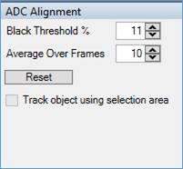
· Black Threshold – this specifies the percentage image brightness that separates dark background (ignored) from bright target (included in calculations). Adjust this until the red shading covers all the background and surrounds (but does not cover) the target.
· Average Over Frames – How many frames of measurement will be taken before updating the graph with a new data point. If you have a noisy image you may want to increase this number.
· Reset – clear historical offset data from the graph.
· Track object using selection area – if you have used the Selection Area tool to restrict the measurements to a certain area of the image then you can check this box to have SharpCap automatically keep the selection area centred on the bright target within it (even if the target moves).
The Alignment history graph shows how the measurement of dispersion has changed over time (due to adjustments made to the ADC).
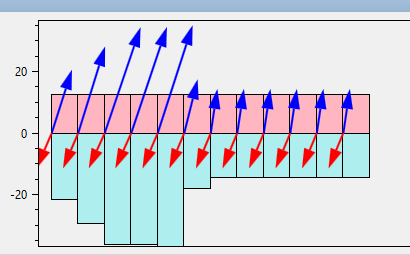
The length of the red line (red-green offset) on the display is tracked by the red columns shown above zero, while the length of the blue line (blue-green offset) is tracked by the blue columns shown below zero. The arrows show both the directions and relative lengths of each line at each measurement.
Newer measurements are continually added on the right hand side of the graph. Once the graph fills up, old measurements will gradually be moved off the left hand side allowing the latest data to be shown on the right.
Alignment Procedure
ADC Alignment is a two-step procedure, first getting the rotation of the ADC correct and then adjusting the amount of correction applied by the ADC to give the minimum possible values for the red and blue offset lines. You can read more about alignment procedure on the Sky Inspector ADC Page or try the procedure below.
Rotation Adjustment
For this stage, set your ADC to the maximum possible magnitude of correction. Once this is set and the ADC alignment tool in SharpCap is ready, gradually rotate the ADC (the camera can rotate too) through 360 degrees. Keep an eye on the size of the offset lines during the rotation. At one point in the rotation, the ADC will be pointing exactly in the wrong direction (180 degrees out) – at this point, the amount of dispersion and the length of the offset lines will be at a maximum, since the ADC and the atmosphere will both be acting to bend the colours in the same direction. At a point 180 degrees away from that maximum you should encounter a minimum value for the dispersion and the length of the offset lines – at this point the ADC is compensating for the atmospheric dispersion, but is over-correcting. Note that during this adjustment phase, the direction in which the offset lines point does not matter – you are only worried about the lengths of these lines and at which points in the rotation the lengths are largest and smallest.
Once you have located these two positions, position the ADC so that you are in the location which gives the smallest dispersion and is roughly opposite the largest dispersion point and move on to adjusting the magnitude of correction.
Magnitude Adjustment
This is a simpler adjustment stage – having completed the rotation adjustment above you know that the ADC is aligned in the correct direction, so it is simply a matter of gradually reducing the amount of correction that the ADC is applying until you get the minimum possible lengths of the two offset lines. Once this point is determined, you may wish to check to see if any small tweaks to the rotation help reduce the offsets further.