Image Processing in SharpCap
SharpCap has a number of controls in the Preprocessing group that allow immediate processing of images as they are captured. These controls are intended for two main purposes:
1. Correction of images when capturing video for Lunar/Solar/Planetary imaging. The following controls would tend to be used:
o Flat correction via Apply Flat to correct for dust spots
o Planet/Disk Stabilization for planetary imaging
o Flip (after dark/flat) for image re-orientation
o Mask over-exposed Pixels for imaging Solar prominences
The processing options selected are applied to captured frames from the camera in real time and the saved video files contain the processed data.
2. Processing of images when Live Stacking. The following controls would tend to be used:
o Dark subtraction via Subtract Dark to correct for hot pixels and thermal noise
o Flat correction via Apply Flat to correct for dust spots and vignetting
o Background Subtraction to remove light pollution and light pollution gradients
o Satellite Trail Removal to suppress streaks from satellite trails
o Banding Suppression to reduce horizontal banding from CMOS cameras
o Flip (after dark/flat) for image re-orientation
The processing options selected are applied to the captured frames before they are incorporated into the stack. However, if the option to Save Raw Frames is enabled in Live Stacking, the saved raw frame files do not includethe effects of image processing.
It is, of course, possible to use the various image processing controls for other purposes in SharpCap, but please note the following:
The effect of enabling controls in the Preprocessing group affects the images saved to disk by SharpCap in both still and video files with the sole exception of saved raw frames when Live Stacking.
Adjustments made to the image data by these controls typically cannot be fully undone by later processing.
Image Processing Controls
The controls in the Preprocessing group appear as shown below. Note that additional controls appear when certain controls (for example Banding Suppression or Remove Satellite Trails) are enabled to allow those actions to be fine-tuned.
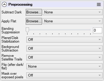
Note that most of these image processing controls are SharpCap Pro features.
Subtract Dark
Subtracts the selected dark frame image from each frame captured by SharpCap, allowing artefacts such as amp glow and dark noise to be reduced. Recently used dark frames are listed in the drop down list along with the special options None, Hot Pixel Removal Only and Hot and Cold Pixel Removal. To select a dark frame from a file, use the Browse button and choose the desired file.
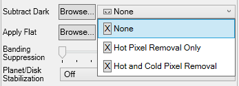
Selecting None from the drop down list disables dark frame subtraction. You can remove recently used files from the drop down list by pressing the ‘X’ button to the left of the file name. Note that the ‘X’ buttons adjacent to the first three special options have no effect.
Selected dark frames must match either the current capture area in use, or must match the full sensor area of the camera if the camera is being used in ROI mode. They must also match the current camera settings such as Colour Space and Read Mode. If you use the camera in ROI mode and select a dark frame that is the full size of the camera sensor, SharpCap will automatically use the correct area of the dark frame based on your ROI settings.
See Capturing and Using Dark Frames for more details.
[Note: the dark frame is subtracted before any other processing of the frame (such as live stacking or any FX effects) and the subtraction of a dark frame affects the saved file.]
Hot/Cold Pixel Removal
For some recent CMOS cameras, both thermal noise and ‘pattern’ noise such as amp glow can be negligible. When using these cameras, dark subtraction may not be necessary, especially when using relatively short exposure times of only a few 10s of seconds. However, hot and cold pixels can still be an issue as they can lead to issues when stacking, so SharpCap now has options to deal with hot/cold pixels without needing full dark subtraction.
The Subtract Dark control has the following additional options are available:
· Hot Pixel Removal Only – this option does not use a dark frame, instead it attempts to remove hot pixels from the camera image by finding pixels that are significantly brighter than any of their neighbours.
· Hot and Cold Pixel Removal Only – this option attempts to remove hot pixels as described above and also attempts to find and remove cold pixels using a similar approach – looking for pixels that are significantly dimmer than any of their neighbours.
When either of these two options are selected, an additional Hot Pixel Sensitivity slider control appears which allows the sensitivity of hot and cold pixel detection to be adjusted. Setting higher values will increase sensitivity and means that more pixels will be detected as hot or cold. It is usually a good idea to look at individual frames with a high magnification and a strong Display Stretch applied when adjusting this sensitivity.
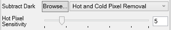
Note that Hot/Cold pixel removal is only truly effective for monochrome cameras or for colour cameras operating in RAW modes. Attempting to use this feature on a colour camera operating in RGB mode will lead to poor results.
Apply Flat
Applying a flat frame corrects each frame for brightness variations caused by vignetting or dust spots. The flat frame correction code has been highly optimized so that on a fast PC it can run on every frame even when high speed imaging using a USB3 camera.
As for dark subtraction, recently used flat frames can be selected from the drop down list, or the special option None can be selected to turn off flat frame correction. Newly created flat frames can be selected by using the Browse… button to select the image file containing the flat frame.
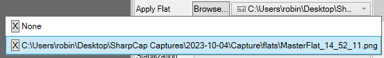
Selected flat frames must match either the current capture area in use, or must match the full sensor area of the camera if the camera is being used in ROI mode. If you use the camera in ROI mode and select a flat frame that is the full size of the camera sensor, SharpCap will automatically use the correct area of the flat frame based on your ROI settings. Flat frames should ideally be in a bit depth of 16 bits, even if the camera is being used in an 8 bit mode.
See Capturing and Using Flat Frames for more details.
[Note: the flat frame correction is applied after dark subtraction but before any other processing of the frame (such as live stacking or any FX effects) and the application of a flat frame affects the saved file.]
Banding Suppression
Some cameras, particularly CMOS cameras, show varying horizontal bands in dark areas of the image (these may only be noticeable after the image levels are stretched to show faint objects). The image below shows a sample of this type of banding:
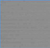
SharpCap’s banding suppression function can help remove this type of banding in each frame from the camera before it is saved or processed.
The Banding Suppression control sets the strength of the banding reduction effect.
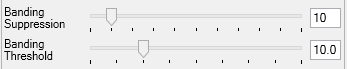
The Banding Threshold control specifies a brightness level above which the banding suppression is not applied – ensuring the adjustments are only made to the darkest parts of the frame where the banding is most visible.
The best way to adjust these controls is as follows:
· Set the camera up to take dark frames
· Use the display stretch if necessary to make the banding more visible
· Initially turn up the Banding Threshold to maximum
· Turn up the Banding Suppression control gradually until you are happy with the amount that the banding has been reduced
· Now turn down the Banding Threshold control gradually – at some point the banding will re-appear because the threshold will have been set too low. Turn the threshold back up a little to make the banding disappear again and you are done.
The Banding Threshold has no effect if Banding Suppression is set to zero.
If you use these controls then you should use the same settings for them for both dark and light frame capture.
Planet/Disk Stabilization
Enabling this option when imaging a planet or a full solar/lunar disk will offset each frame image to place the planet/disk in the centre of the frame.
If this option is enabled when imaging other types of target, particularly ones that fill the entire camera frame, the results may be unpredictable.
Stabilizing the planet/disk to the centre of each frame affects both the image as shown on screen and the image data saved to any image or video files.
Because the image is being moved, areas that are outside the recording area of the camera may be brought into view – they will show in as black with a thin red line highlighting where the edge of the actual camera image is.
This feature may be most useful for the focusing stage – by keeping the planet in a constant location, judging the point of best focus either by eye or using SharpCap’s focus tools will be easier.
Planet/Disk Stabilization is only available for cameras that are running in live view mode. If your camera is running in Still Mode, this control will not be available.
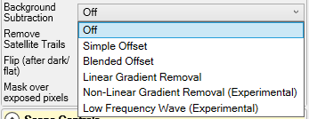
Background Subtraction
Enabling this option will remove a background level from each frame. This will help remove the background brightness caused by light pollution (sky glow), and in particular help remove any colour cast to the background of the image due to light pollution.
This option is designed to be used where there is a significant amount of light pollution to be removed. If you have very dark skies or are using narrow band filters, you may find that this option brightens the background of your image slightly, since it tries to adjust the background level of each colour channel to the 5% point on the histogram, rather than to absolute blackness.
This option is compatible with dark and flat frame correction, and should ideally be used with both (or at least dark frame correction). Dark frames remove the unwanted brightness caused by the camera itself, this option removes the unwanted brightness caused by light pollution.
The adjustment made to the image brightness may be different for the different colour channels in colour images (this allows correction for a coloured sky glow). The correction however does not vary with position in the image, so gradients in sky glow will not be removed.
Enabling this option will affect both the image shown on screen and the image data saved to file when capturing.
There are various options for Background Subtraction, which change the details of how the background to be removed is calculated:
· Simple Offset – will apply the same, auto-detected correction to all pixels in the image. This may affect the colours of bright stars as (for example) an orange/red sky glow will lead to the largest reduction being applied to the red channel, possibly making bright stars take on a blue/green hue.
· Blended Offset - will cause SharpCap to avoid making such large adjustments to the brightness of pixels that are close to full brightness – this will reduce or eliminate any shift in star colours caused by the background subtraction option. This option should be preferred in most cases over ‘Simple Offset’.
· Linear Gradient Removal – rather than use a single, constant, background value across the entire frame, in Linear Gradient Removal mode, SharpCap will look detect and remove gradients in background brightness across the frame. The brightness adjustments are applied in a manner similar to Blended Offset to avoid colour changes to bright stars.
This option can detect horizontal, vertical and diagonal gradients. It should be used with caution in cases where nebulosity covers all or most of the frame, as it may mistakenly detect brightness patterns in the nebulosity as a background gradient.
· Non-Linear Gradient Removal (Experimental) – this option attempts to fit a second order polynomial curve to the background brightness of the image to allow removal of gradients that do not vary linearly across the image.
In cases where the background is correctly detected, this approach will remove it more effectively than the Linear Gradient Removal. However, this approach has more freedom to produce different shapes of background (6 free parameters per colour channel rather than 3), so there is increased scope for this option incorrectly picking up other patterns in the brightness of the image such as variations in nebulosity. As such, it should be used with caution.
· Low Frequency Wave (Experimental) – this option attempts to fit a combination of linear gradient and sine and cosine waves (with a wavelength equal to the image dimensions) to the background brightness pattern of the image. The same cautions as for Non-Linear Gradient Removal (Experimental) apply – this option has 11 free parameters so may give a better fit to background gradients but may also incorrectly attempt to fit to other brightness patterns in the image.
DO NOT capture calibration frames (flat, dark, bias, dark flat, etc) when this option is enabled. This option should only be used when capturing light frames.
Remove Satellite Trails
The increase in the number of artificial satellites in recent years has caused significant issues for both amateur and professional astronomers, as the satellites can often be in a high enough orbit to still catch and reflect sunlight even when it is dark on the ground. These satellites frequently leave bright trails across long exposure images, meaning either that the image with the satellite trails needs to be discarded or that the trails needs to be hidden or edited out in some way.
SharpCap’s Satellite Trail Removal feature attempts to automate the detection and removal of satellite trails from camera images without needing human intervention except in the setup phase. When correctly configured and enabled, SharpCap will detect bright streaks in the image that are caused by satellite trails and replace those parts of the image with data from nearby pixels unaffected by a satellite trail.
When correctly set up, this can detect most satellite trails and reduce the brightness of detected trails by 90% or more. It is worth noting that the calculations required for satellite trail detection and removal are extensive, and this feature can take several seconds to process each frame (particularly for high resolutions or slower CPUs). Only use this feature while capturing longer exposure images. SharpCap will automatically disable this feature during sequencer based autofocus procedures, but you should consider disabling it manually when the exposure time is reduced for any reason (focusing, plate solving, etc).
Configuring Satellite Trail Removal
Satellite trail removal has two active modes (in addition to being Off), which can be selected using the dropdown list:
· Test (Highlight Trails) – this mode is for use when configuring the trail removal settings and should not be used when capturing or live stacking. When this mode is enabled, detected trails will be highlighted in the image, making them more obvious. This helps you tell whether the current settings are correctly detecting any satellite trails in the image.
· Remove – this mode is the mode for actually removing satellite trails. In this mode, any trails that are detected are wiped out with pixel data taken from nearby areas of the image. This mode should be used when capturing or live stacking.
In either of the two active modes, additional options appear below the main Remove Satellite Trails option, giving control over the sensitivity of trail detection and other aspects of the removal. The effects of these controls and the best way to adjust them are discussed below.
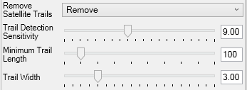
· Trail Detection Sensitivity – this controls how sensitive the satellite trail detection scanning is. Higher values will help detect fainter trails but will lead to increased calculation times and may also lead to false positives (trails detected over other image features) in some cases.
· Minimum Trail Length – this is measured in pixels and specifies the shorted fragment of satellite trail that will be detected. Lower values will help detect slower moving satellites that might only have a short trail segment in each image. Lower values will also help detect trails that have just entered or just left the frame. On the flip side, low values will increase the likelihood of false positives, particularly if combined with high Trail Detection Sensitivity.
· Trail Width – this affects both detection and removal of the trail. Set lower values of this control to detect narrow satellite trails and higher values to detect wider trails. The area of image that is replaced when a trail is detected is also controlled by this parameter, so higher values can help if the Remove mode is not removing the trail entirely.
The best technique to use to adjust the settings is as follows:
1. Review previously captured images or capture new images and find frames containing satellite trails. Note that it is important that these are individual frames from the camera, not stacked images.
2. Open the SharpCap Test Camera 1 (Deep Sky) and use the Browse… button on the Image control in the Testing Controls group to select one of the images with satellite trails that you identified in stage 1.
3. Use the Display Stretch control to stretch the display and make the satellite trail clearly visible
4. If desired, set the Exposure/Gain Shift control to -3, which will give 1s exposures for faster feedback without affecting image brightness
5. Set the Remove Satellite Trails control to Test (Highlight Trails)
6. Adjust the Trail Detection Sensitivity and Minimum Trail Length to ensure that the satellite trail(s) in the image are detected and over-drawn with white. Do not set the sensitivity higher than necessary to minimize the chance of false positives.
7. Ensure that no other white lines are being drawn on the image (false positives)
8. Set the Remove Satellite Trails control to Remove and check that the trails are being removed from the image. Adjust Trail Width if needed
9. Repeat for other images with satellite trails in them.
Note that the settings will need re-adjustment if you change telescope or camera, and may need re-adjustment for different camera settings (exposure lengths, binning, etc).
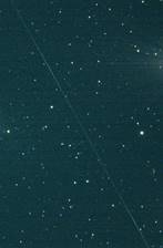
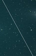
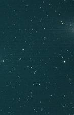
Typical results
The following four images show (from left to right):
· A satellite trail in a strongly stretched deep sky image
· The satellite trail being detected by the Test (Highlight Trails) mode
· The satellite trail being removed by the Remove mode
· A closeup of the removed trail, showing that some trace is still visible, but much reduced
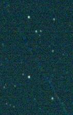
While traces of the trail are still visible after the removal procedure, they are much reduced and they will vanish quickly when processed images are stacked.
Flip (after dark/flat)
This control provides an alternative to camera provided Flip controls with the following advantages:
· Available for all cameras rather than just a selection
· Does not require separate dark or flat frames to be used for each Flip orientation because the flip is applied after the dark and flat processing.
This control should be used in preference to camera-provided Flip controls in the Camera Controls or Image Controls groups. Those camera-provided options may be removed in a future version of SharpCap.
The options available for the Flip (after dark/flat) control are:
· None – no flip applied
· Horiz – flip horizontally – that is left becomes right and right becomes left
· Vert – flip vertically – that is top becomes bottom and bottom becomes top
· Both – flip both horizontally and vertically, which is equivalent to a 180 degree rotation of the image
Mask over-exposed Pixels
This option is designed primarily for use when capturing images of solar prominences using narrow band solar filters. When the camera is set up to properly expose prominences, the disc of the sun will be over-exposed and bright white, which can be distracting. Enabling this option will set over-exposed pixels in the image to black, which will effectively mask out the disc of the sun.
The effect of turning on this option are shown below. It is particularly useful when live broadcasting solar imaging sessions, since the same effect can be applied in processing when stacking captured videos.
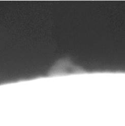
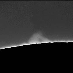
Image Processing Ordering
SharpCap performs image processing in the following order (processing options that are disabled are obviously not run).
· Hot/Cold pixel removal
· Row noise suppression
· Dark Subtraction
· Flat frame correction
· Image stabilization
· Satellite trail removal
· Flip (after dark/flat)
· Mask overexposed pixels
Capturing and Using Dark Frames
Introduction to Dark Frames
Images taken with digital cameras can suffer from noise caused by the camera sensor and electronics. Dark frames can be used to counteract some of the effect of this noise on image quality. A dark frame is taken with the camera lens (or telescope) covered to ensure there is no light, but otherwise with exactly the same camera settings as used for capturing light frames. This means any signal in the dark frame is due to noise, not due to light. In particular, the dark frame may contain signal due to:
· Thermal Noise – this results when electrons in the imaging sensor are collected as a result of heat rather than as a result of detecting incoming photons. The effects increase with longer exposure, but can be decreased by cooling the camera sensor
· Pattern Noise (sometimes called ‘amp glow’) – this results from a number of potential causes but typically manifests as a glow in one or more areas of the sensor that becomes apparent in long exposure, low light, images
· Hot, Cold, Warm and Cool Pixels – these are individual pixels in the image which produce abnormal values, particularly for longer exposures. Hot pixels may produce maximum or near maximum output value without any significant light input, warm pixels produce higher than typical output value, cool and cold similar in the opposite direction.
Subtracting the pixel data of the dark frame away from the pixel data of each light frame can remove or reduce the effects of these types of noise in the light frame data.
The dark frame must be captured under identical conditions (such as exposure, gain, resolution, temperature) as the image frames for the noise to cancel correctly.
It is good practice to capture many dark frames and average them together, rather than just capturing a single dark frame. In fact, ideally, you should capture as many dark frames as light frames!
For best results, the dark frames should also be captured with the camera sensor at the same temperature as when capturing light frames. Many cameras have a temperature sensor (the value will be displayed in the SharpCap camera controls) to help you judge this. Some cameras have a Peltier thermoelectric cooler attached (a fridge on the back of the camera) to combat noise generated by heat from long exposures, this also usually allows the temperature of the camera sensor to be controlled, which is ideal for dark frame capture.
Capturing Dark Frames in SharpCap
This subsection explains the process for capturing and saving a dark frame. The process is started from the main menu via Capture > Capture Dark. The telescope or camera must be covered to exclude any light before commencing the dark frame capture. The process produces a single ‘master dark’ frame that contains the image data averaged from multiple individually captured dark images. This ‘master dark’ frame can then be used in the Subtract Dark control in SharpCap or as a master dark frame in other processing software.
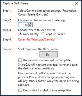
While the Capture Dark Frame window is open, do not use any SharpCap functions. Additionally, while the darks are being captured (after pressing the Start button), do not adjust any camera controls. Once the window closes, the dark frame capture process has completed.
The options that can be specified when capturing dark frames are as follows:
· Number of frames to average – This tells SharpCap how many dark frames to capture and average together. Actually, SharpCap will normally capture one extra frame in addition to the number specified here and will discard the first frame – this helps avoid problems if the telescope/camera has only been covered part way through the first frame
· Where to save the file – SharpCap can save the resulting dark frame to either the Dark Library or the normal capture folder.
· Use new dark when capture complete – when this box is checked, SharpCap will automatically select the newly created dark frame at the end of the Capture Dark process
· Keep individual dark frame image files – when this box is checked, the individual dark frame files will be kept for later manual processing or re-use. When the box is not checked the individual image files will be stored in a temporary folder and deleted when the Capture Dark process is complete.
The following camera settings should not be used when capturing a dark frame:
· Flat frame correction, Background subtraction or any other option in the Preprocessing group
· Any ‘Auto’ control values – i.e. auto gain, auto exposure, auto colour balance
Other camera settings should be set to the same value as when capturing light frames. This is particularly critical for settings that affect the image brightness, including:
· Exposure, Gain, Offset/Black Level/Brightness
· Colour balance controls
· Gamma/Contrast and other image adjustment controls
· Flip controls provided by the camera in the Camera Controls or Image Controls groups
Ideally, the temperature of the camera sensor should be the same when capturing darks as when capturing light frames. With a cooled camera, this is easy to achieve. With an un-cooled camera, it is often best to capture dark frames immediately before or after capturing light frames so that air temperature and other conditions are as similar as possible.
The dark frame will be saved in a file format that is chosen as follows:
· The selected Output Format is used if it is a still image format and it supports 16 bit images. If not then…
· The Preferred Still Format is used if it is a still image format and it supports 16 bit images. If not then…
· The FITS file format is used.
Note: If you decide to run your camera in ROI mode, SharpCap can use either a dark frame taken for a matching ROI (the size and position must be the same) or a dark frame taken at the full resolution of the camera. If a full resolution dark frame is used, SharpCap will automatically select the correct sub-area of the dark frame.
The SharpCap Dark Library
When capturing darks and selecting to save the resulting files to the Dark Library, SharpCap will organise the captured files inside a folder called ‘darks’ inside the main capture folder.
The saved files will be further organised into folders by camera name, colour space and capture resolution, exposure length, gain and other camera settings.
For instance, using an Altair GP130M camera, when capturing 10 frames for to make a dark frame, a folder structure is created. The folder structure represents the camera settings in the Camera Control Panel.
|
|
|
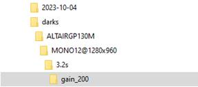
In the folder gain_200 the dark frame set is stored, along with a capture settings file that records the full camera settings used during the capture:
![]()
This arrangement of dark frames makes it easier to find the appropriate frame to use at a later date, particularly as the Browse… button for the Subtract Dark control will automatically chose the most appropriate folder within the dark library to select a dark frame from, based on the current camera settings.
Capturing and Using Flat Frames
Introduction to Flat Frames
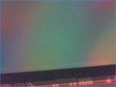
Flat frames are used to correct images for unwanted brightness variations across the frame. This brightness variation might be caused by the optical configuration of a lens or telescope meaning that less light reaches the edges and corners of the frame, making them darker (known as vignetting), or by the presence of dust or dirt specks on the sensor, sensor glass or filters. Dust specks cause dark patches on the image which may be simple spots (as seen in the image below) or small dark donut shapes when using telescopes with a central obstruction.
Dust spots and vignetting need to be corrected before images are stacked as the differing alignment of frames during stacking will spread them out in an unknown manner, making them impossible to fully correct after stacking.
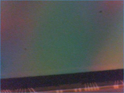
In order to correct for these types of defects in the image, a flat frame is captured – that is an image of a perfectly uniformly illuminated surface, meaning that the only variations in brightness of the flat frame are due to the effects of vignetting and/or dust. The image below shows a flat frame taken with the same (rather dirty) camera sensor used above – the dust specks are clearly visible in the flat frame.
It is actually good practice to capture many flat frames and then to average them to produce a ‘master flat’ which will have less noise that any individual flat frame. The flat frame image shown above is actually a master flat created from 30 individual flat frames and is noticeably less noisy than the light frames shown.
Flat frame correction itself involves brightening the captured image in areas where the flat frame is dimmer than average to correct for the reduction in light reaching the camera sensor in that area. Taking the image and flat frame shown above, the corrected image can be seen below – it is basically impossible to see the effects of the dust spots in the corrected image.
Note: Flat frame correction can also help remove the effects of optical interference patterns from images, such as the ‘Newton’s Rings’ which may cause issues in solar imaging.
Creating Flat Frames
Select Capture Flat from the Capture menu. This will automatically enable the histogram and show the Capture Flat Frame window.
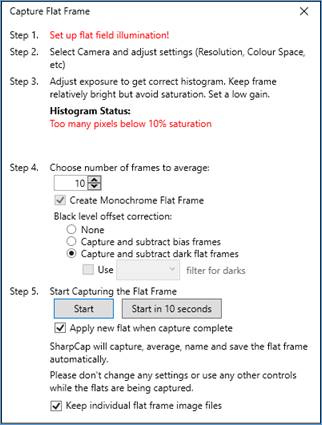
The steps required for creating the flat frame can now be followed
Setup Flat Field Illumination
This involves arranging for the objective or primary mirror of the telescope or camera to be illuminated evenly, ensuring that the only variations in brightness of the captured image will be due to dust specks, vignetting etc.
This is perhaps the trickiest part of using flat frames. Many discussions of different ways to achieve this can be found online, but to give a brief summary, some options are
· Covering the end of the telescope with a white t-shirt and using any light source
· Pointing the telescope at clear blue sky
· Pointing the telescope at uniform, overcast sky
· Using an electroluminescent panel
Note that you should ensure that orientation and arrangement of the imaging system is not changed between capturing flat frames and capturing the actual target images – this means that you should not
· Rotate the camera
· Remove and re-insert the camera
· Add/remove or change filters, reducers, barlows, etc
· Adjust focus more than absolutely necessary (small tweaks are OK)
Setup Camera Settings
Ensure that the camera is set to the correct settings at this stage. If you intend to image at 1600x1200, bin 1, RAW12 then set the camera to those settings before capturing flat frames. There is no need to use the same exposure or gain for flat frames (in fact this would not normally work). Since flat frames should have as little noise as possible, it is usually a good idea to set a low gain value.
Adjust Exposure to get correct Histogram Shape
Correct exposure is critical for creating good flat frames. The text under in the Histogram Status area of the Capture Flat Frame window will provide guidance on how to achieve this.
An ideal flat frame histogram would have a peak at about the 50-60% level and have all the histogram between the 20% and 80% levels. This is shown below for monochrome and colour cameras
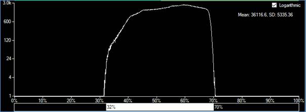
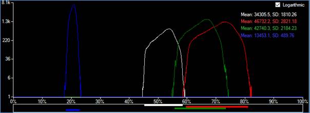
Note the use of the Logarithmic histogram style in both cases which makes it easier to see the extent of the histogram. Also note that for the colour camera the difference in brightness between the blue and red pixels means that it proved impossible to keep all the histogram for both of those colours in the 20-80% range, but the white channel histogram is well confined to the 45-60% region.
Choose Options
The Capture Flat Frame window allows you to customize the flat frame creation procedure by changing the following options
· Number of Frames to Average - SharpCap will capture this number of frames and then create a master flat frame by averaging the captured frames. The higher the number chosen here, the less noise will be apparent in the final master flat frame, which ensure help final image quality.
· Create Monochrome Flat Frame – Selected by default and only relevant for colour cameras, this option will make the created flat frame monochrome even on a colour camera. Monochrome flat frames will only affect the brightness of the image when used. When unselected, a colour flat frame will be created which will have the effect of altering the white-balance of captured images when used.
· Black Level Offset Corrections – Allows a choice of how to correct for the ‘black level’ value of the camera – that is the pixel value given to pixels that have received no light not being zero. The possible options are:
o None – this option is not usually recommended, but may be sufficient for use for removal or reduction of dust spot shadows for Lunar/Solar/Planetary imaging where the images will not be stretched.
o Capture and subtract bias frames - If selected, SharpCap will set the camera exposure to minimum after capturing the flat frames and then capture an equal number of bias frames. The master flat frame will then be made up of the average of all the bias frames subtracted from the average of all the flat frames. Selecting this option should give good flat correction across a wide range of image brightness, particularly when the exposures used for flat frame capture are short (less than about 1s).
This option produces flat frames that can be used without needing dark frames to be used for Lunar/Solar/Planetary imaging purposes, and should be used when creating flat frames for those purposes.
o Capture and subtract dark flat frames – If this option is selected, SharpCap will capture dark flat frames (at the same exposure length as the flat frames) after completing the capture of flat frames. This option can give the best flat correction results (particularly with long exposure flat frames of 1s or more). When using this option, you must either cover the telescope when prompted to allow dark flat frames to be captured or specify a filter to use that blocks light to the camera.
· Apply new flat when capture complete – this option, which is enabled by default, causes SharpCap to automatically start using the new flat frame when the capture and averaging of the flat frames is complete. When unticked, the new flat frame will only be saved.
· Keep individual flat frame image files - when this box is checked, the individual dark frame files will be kept for later manual processing or re-use. When the box is not checked the individual image files will be stored in a temporary folder and deleted when the Capture Flat process is complete.
Start Capturing Flat Frames
Press the Start button to begin capturing flat frames (and bias frames if that option is selected). If the Apply New Flat when capture complete option is checked then the newly created master flat frame will be automatically selected when it is ready.
You can also choose to use the Start in 10 seconds button – this will delay for 10 seconds before beginning to capture the flat frame. This can be useful if you find it hard to get the flat illumination set up and also reach the computer mouse/keyboard at the same time (for instance if you take flats by holding an electroluminescent panel by hand).
Note: The following camera settings should not be used when capturing a flat frame:
· Background subtraction, banding suppression, Planet/Disk stabilization or any other option in the Preprocessing group except for Subtract Dark
· Any ‘Auto’ control values – i.e. auto gain, auto exposure, auto colour balance
Using Flat Frame Correction
Flat frames can be selected by using the Apply Flat control in the Pre-processing group.
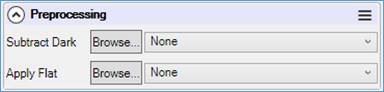
Press the Browse button to select a flat frame that has already been saved to disk or use the drop down to select a recently used flat frame. To disable flat frame correction, select None from the drop down.
Note: If you decide to run your camera in ROI mode, SharpCap can use either a flat frame taken for a matching ROI (the size and position must be the same) or a flat frame taken at the full resolution of the camera. If a full resolution dark frame is used, SharpCap will automatically select the correct sub-area of the flat frame.
Note: If your camera has ‘Flip’ controls in the Camera Controls or Image Controls groups, flat frames must be captured in the same flip settings as light and flat frames. Prefer to use the Flip (after dark/flat) control to using the Flip control provided by the camera.
Note: Flat frames created by other software can be used by SharpCap providing they are saved in a compatible format (PNG, FITS, TIFF)
Applying flat frame correction will affect both the image shown on screen and the image data saved to any capture file, so there is no need to apply flat frame correction in later processing if you have used flat frame correction in SharpCap.
Flat frame correction in SharpCap is possible even with high speed cameras – with the LifeCam Cinema running at 1280x720x30fps, applying a flat frame only increases the CPU usage by 1% – SharpCap uses the special video processing instructions in modern CPUs to apply flat frames incredibly efficiently. With a fast CPU you can apply a flat frame to a USB3 camera running at 1920x1080x150fps!
Getting good Flat Frame Correction
Getting good flat frame correction can require some care and attention. If you are taking deep sky images and intend to stretch the final image as part of the processing procedure (either using SharpCap’s life stacking or an external stacking/processing application) then you will need to take much greater care than if you are using flat correction to remove dust shadows from lunar/solar/planetary images. The stretching of the image that is an almost invariable part of deep sky imaging will make any inaccuracies in the flat frame correction much more noticeable.
For deep sky imaging, the following procedure for capturing and using flat frames is recommended:
· When capturing flat frames either use the option to subtract bias frames or the option to subtract dark flat frames.
· When capturing light frames, always use dark frame subtraction and ensure that the dark frames are captured at the same camera settings and temperature as the light frames.
Note: failure to use a dark frame when capturing the light frames will tend to result in the flat frames over correcting (previously dark areas become brighter than average). Failure to use either the subtract bias option or dark flat frames will tend to result in flat frames that under correct.
For lunar/solar/planetary imaging, the following procedure is recommended instead:
· When capturing flat frames use the option to subtract bias frames. Using a dark flat frame should not be necessary
· When capturing light frames, do not use a dark frame - SharpCap will use the offset information in the flat frame to account for the pedestal offset in the image.
· Take the light and flat frames with (as much as possible) the same camera settings. In particular, do not change the offset/black level/brightness control or the colour balance controls, and avoid changing the gain if you can.