Camera Controls
Generic camera controls are described below in Common Camera Controls.
Subsequent subsections describe features specific to individual camera manufacturers. The same functionality may have different names across manufacturers. Different models from the same manufacturer may have differing features. The manufacturers are described in alphabetic order.
Common Camera Controls
The controls listed below are generally expected to be available across a wide range of cameras from different manufacturers, although not all cameras will have every control listed in this section. These controls are to be found in the Camera Control Panel (which by default is shown to the right of the main camera image).
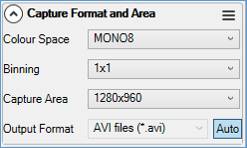
Capture Format and Area
|
Capture Format and Area |
|
|
Colour Space |
· The colour space control determines the image format each frame is captured in. In general, there are four categories of colour spaces o Monochrome o Colour o Raw o Compressed · See Colour Spaces Explained for more detail on the colour space to choose and the implications of each choice. |
|
Capture Area |
· This controls the size (in pixels) of each frame captured. · For most cameras, the choice of a smaller capture area selects capture of a subarea of the full sensor area – this is often termed ROI (region of interest) capture. · As well as giving smaller saved files, selecting a smaller capture area often gives a higher frame rate. |
|
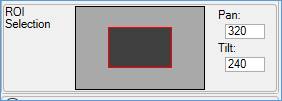
ROI Position (pan/tilt) |
·
When a smaller capture area is selected, it is usually also
possible to choose which region of the sensor is used – selecting
the appropriate Region of Interest
(ROI).
· Only shows if the selected ROI is smaller than the maximum. |
|
Binning |
See Binning below further information. |
|
Output Format |
· Output format allows the choice of the format any captured files will be saved in. The options for capture format can be found in Capture Formats Explained. The following rules apply: · For 'Snapshot' (single frame) captures, one of the still capture formats (PNG, FITS, TIFF and JPEG) are always used, even if the selected output format is a video format (AVI or SER). If the output format is a still file format the selected format is used. · For video captures, the selected format is always used. If a still file format is selected each frame will be saved to a separate file. When the output format is set to ‘Auto’, a compatible video format is selected if the current exposure is less than 5 seconds and a compatible still format is selected if the current exposure is greater than 5 seconds. The preferred output formats specified in the settings dialog are used (providing the preferred format is compatible with the type of image being captured – for instance 16-bit depth images cannot be saved to AVI format).
[Note: If the ‘Start Cameras with Auto Output Format’ option is checked in the General Tab of the settings then cameras will always start with this control in ‘Auto’ mode.] |
|
Debayer Preview |
· Only shows for RAW colour spaces. · Allows the user to choose to debayer (convert to colour) or not the raw image for display. · Does not affect the data saved to file. · As well as switching the debayer function on and off it is possible to override the Bayer pattern used if, for some reason, the wrong pattern is selected automatically. |
Binning
Binning is a technique used to improve the
signal-to-noise ratio of an image at the expense of reducing the
resolution. Binning works by taking the value of 2 or more
neighbouring pixels on the sensor and either adding or averaging
them to produce the value for a single output pixel. Binning
is usually 'symmetric' - meaning that the same number of pixels are
averaged over in each direction. For instance, a binning value of
'2x2' or just '2' means that a 2 by 2 block of sensor pixels are
used to make each pixel in the final image – this will reduce the
resolution of the final image by a factor of 2, but also increase
the signal-to-noise ratio (S/N ratio) of the image by a factor of
2.
As an example, with a 1280x960 sensor, using 2x2 binning will give
an output image of 640x480. Using 4x4 binning will give an output
image of 320x240.
A binning value of '1' or '1x1' means that no binning is being
applied.
It is important to note that some cameras add pixel values when
binning (meaning that the image will get brighter when binning is
turned on), while other cameras average the values (meaning that
the image doesn't get brighter, but the noise reduces
instead). In both cases, the same increase in S/N ratio is
achieved in the final image – if a brighter image is required and
the camera averages then just turn up the gain – the result being
the same as if the camera had added pixels.
Additive Binning
|
|
|
|
Unbinned (width 2x, height 2y) |
Binned 2x2 (width x, height y) |
Additive binning – no other changes were made to camera settings between the unbinned and binned images. Applying the 2x2 binning halves the size of the captured image and brightens the image by a factor of four. Note that a considerable level of noise is visible in the brighter right hand section of the image in both frames.
Averaging Binning
|
|
|
|
|
Unbinned (width 2x, height 2y) |
Binned 2x2 (width x, height y) |
Binned 2x2 with extra gain (width x, height y) |
Averaging binning – no other changes were made to camera settings between the unbinned and binned images. Applying the 2x2 binning halves the size of the captured image but does not brighten the image in this case. However, looking closely at the bright area on the right-hand side of the image shows that applying the binning has significantly reduced the noise in this area (and across the rest of the frame). Increasing the gain further does brighten the binned image producing a similar image to the additive binning result both in terms of image brightness and noise level.
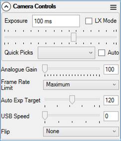
Camera Controls
|
Camera Controls |
|
|
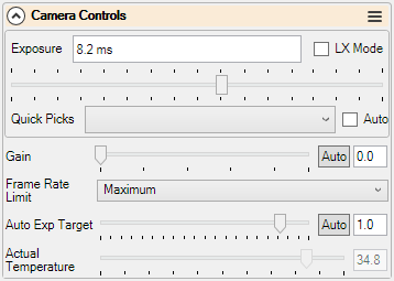
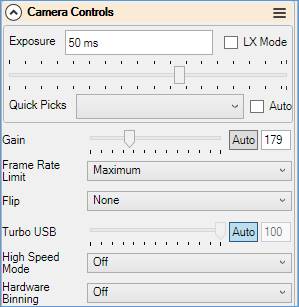
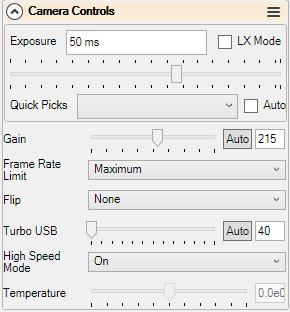
Exposure |
· Exposure controls the length of time that the camera collects photons for each frame. · Longer exposures allow more photons to be collected and will therefore give brighter images. · For most cameras, the selection of a longer exposure can limit the frame rate. For instance, setting an exposure of 100ms (1/10s) will limit most cameras to a frame rate of 10 frames per second. · Each camera will have its own limits for the length of exposure it allows. · Some cameras (particularly webcams) may report incorrect ranges of allowable exposures to SharpCap. · The LX checkbox in the exposure control has only one effect – it changes the range of the exposure slider from minimum exposure to 5s (LX unticked) to 0.5s to maximum exposure (LX ticked). This is necessary because for cameras with a very wide possible exposure range it becomes difficult to adjust the exposure accurately if the slider range runs all the way from 0.01ms to 1000s. |
|
Gain |
· The gain control acts as an amplifier for the signal received by the sensor. · Turning up the gain will increase the brightness of an image without needing to increase the exposure duration, but at the cost of the making the image noisier. |
|
Frame Rate Limit |
· Limits the rate at which frames are processed by SharpCap, even if the camera is creating frames at a higher rate. · This affects the rate at which frames are saved to any capture file and the rate at which the UI is updated. |
|
Flip |
· Apply a horizontal or vertical (or both) flip to an image to correct its orientation. |
|
Temperature [Read Only] |
· The current temperature of the camera sensor. Note that if the camera has more complicated thermal controls (for instance a Peltier cooler), the current temperature will appear with those controls in the Thermal Controls section. |
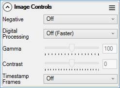
Image Controls
|
Image Controls |
|
|
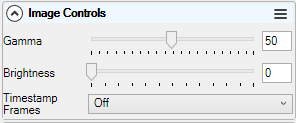
Gamma |
· Neutral gamma is 1. · Correctly interpreted, gamma of less than 1 will boost the shadows and mid tones, gamma greater than 1 will lower the mid tones and highlights. · Some applications and cameras treat gamma the opposite way around – increasing gamma boosts the shadows. · See http://www.orpalis.com/blog/color-adjustments-brightness-contrast-and-gamma/ for more details on gamma, contrast and brightness. |
|
Contrast |
· Increasing contrast will typically make the dark pars of the image darker and the bright parts brighter. · Sometimes this can help pull out detail in the image. |
|
Brightness |
· Increasing brightness will typically make the image brighter by the same amount. · This can help pull out detail in the darker regions of the image. |
|
Timestamp Frames |
· Applies a UTC timestamp in the top left corner of the frame. · As well as the visible timestamp a machine-readable timestamp is embedded into the first 8 bytes of the pixel data of the frame. The machine-readable timestamp is a 64-bit integer that is the number of 100ns intervals since midnight on 1st Jan 0001 (see https://msdn.microsoft.com/enus/library/system.datetime.ticks(v=vs.110).aspx for defaults) |
|
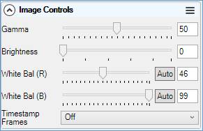
White balance |
See White Balance below. |
White Balance – Images shown from colour cameras can frequently show incorrect colours. This can be due to a range of reasons, such as:
· One colour (often green or red) being more sensitive to light than the other colours.
· The type of illumination the image is being taken under – for instance tungsten, LED or fluorescent lights for non-astro images.
Different cameras have different controls to enable colour balance to be adjusted to give images showing the correct colours.
Although these controls differ in detail they all effectively allow the brightness of the colour channels to be adjusted relative to each other to correct the colour cast in the image.
Some cameras offer an auto white balance option – these often work well for ordinary images but can sometimes be confused by astro images, so should be used with caution.
Use the histogram control while adjusting the white balance and other image controls such as gamma, contrast and brightness – if it is noticed the histogram trace for any of the colour channels has gaps (i.e. levels with zero count appear in the middle of the histogram – see graphic below), it probably means the white balance (or other) adjustment is being done in software on the PC rather than in hardware on the camera. Histograms such as the one below indicate data is being lost.
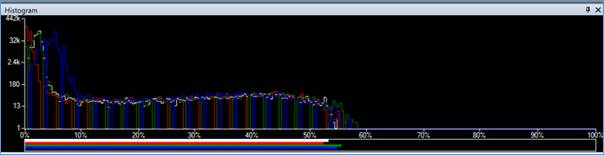
In this case, it is best to set the white balance back to default (remove the gaps in the histogram) and to correct the colour balance after stacking. This will avoid the data loss caused by applying digital white balance correction in SharpCap.
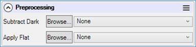
Pre-processing
|
Preprocessing |
|
|
Subtract Dark |
· Subtracts the selected dark frame image from each frame captured by SharpCap, allowing artefacts such as amp glow and dark noise to be reduced. See Capturing and Using Dark Frames for more details.
[Note: the dark frame is subtracted before any other processing of the frame (such as live stacking or any FX effects) and the subtraction of a dark frame affects the saved file.] |
|
Apply Flat |
· Corrects each frame for brightness variations caused by vignetting or dust spots. The flat frame correction code has been highly optimized so that on a fast PC it can run on every frame even when high speed imaging using a USB3 camera. See Capturing and Using Flat Frames for more details.
[Note: the flat frame correction is applied after dark subtraction but before any other processing of the frame (such as live stacking or any FX effects) and the application of a flat frame affects the saved file.] |
Mini Histogram and Display Stretch
This control shows an always-on mini histogram of the current image and allows the image displayed on screen to be ‘stretched’ without affecting the data saved to file when capturing. Stretching the displayed image means that the brightness and/or contrast can be enhanced, or faint detail can be brightened easily. The stretch function provides similar effects to the Image Boost options in the FX dropdown but with finer control.
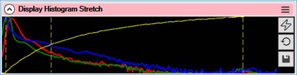
Adjusting the Display Histogram Stretch
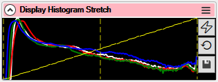
Basic operation of the stretch adjustments involves dragging the position of the three vertical dashed yellow lines using the mouse. These three lines represent the histogram levels that will be displayed as black, mid grey and white respectively.
It is usually most useful to adjust the black and mid-level lines. Adjusting the mid-level line so that it is no-longer half way between the black and white level lines will create a transfer curve, shown as a yellow curve on the histogram that controls how the image pixel values are converted to displayed screen brightness.
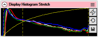
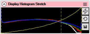
Moving the mid-level line to the left will create a curve that initially rises rapidly then flattens out. This will have the effect of boosting the brightness of the darker areas of the image, making it easier to see faint detail. Moving the mid-level line to the right will create a curve that is initially relatively flat before rising more sharply near the white level. This has the effect of darkening the brighter areas of the image, perhaps making more detail visible in those regions.
The default settings of the Display Histogram Stretch (image displayed without adjustment):
The mid-level line moved to the left, enhancing the brightness of faint detail:
The mid-level line moved to the right, enhancing contrast in bright areas of the image:
Moving the black-level line to the right will effectively darken the whole image. This can be useful to give a blacker background – making background noise and light pollution less noticeable.
Display Histogram Stretch Buttons
![]()
The top, lightning bolt, button will perform an auto-stretch designed to pull out faint detail in the current image. This will adjust the black, mid and white level lines automatically based on an analysis of the brightness levels in the image. You can adjust how strong a stretch will be applied when using this button in the General Tab of the SharpCap settings. Using the auto-stretch feature requires a SharpCap Pro license.
![]()
The middle, circular arrow, button will reset the black, mid and white level lines back to their default positions, removing any display stretch currently in effect.
![]()
The bottom, save, button will save the current image exactly as seen onscreen as a PNG file. Unlike the normal SharpCap image saving functionality, this saved file *will* include the effects of any display stretch currently in effect. Note that the saved image file will have a bit depth of 8 bits regardless of the bit depth setting of the current camera.
Any changes made in the Display Histogram Stretch section only affect how the images are displayed on screen – there will not be any changes made to the images saved to capture files (except those saved using the ‘Save Exactly as Seen’ button in the display histogram stretch control.
Camera Specific Controls
The controls listed below will appear in addition to the common controls listed above.
Altair Camera Controls
SharpCap supports all current models of camera produced by Altair Astro. If the camera is a new model and not in the Cameras list, please check for an updated version of SharpCap which may include changes needed to support the camera.
Further information can be found at the Altair Astro website. Drivers, software and technical notes can be found at the Altair Support website.
|
Image Controls |
|
|
White Balance Adjust |
Performs a single auto adjustment of the image white balance. |
|
Negative |
Converts the image to a negative representation (black becomes white, white becomes black, colours are reversed). |
|
Colour Tint |
Adjust the green/magenta colour balance of the image – lower values give a magenta tint to the image, higher values a green tint.
|
|
Colour Temperature |
Adjusts the red/blue colour balance of the image – setting this value higher will make the image appear redder, setting it lower will make it appear bluer.
|
|
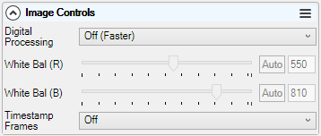
Digital Processing (On/Off) |
Enables/Disables the digital adjustments to the image in the Altair Driver. · When this is switched to 'On', controls like Gamma, Brightness, Colour Tint, etc. are active. · When switched off, these controls are disabled. Switching this to Off may give a small performance boost. |
|
Camera Controls |
|
|
Auto Exposure Target |
Controls the how bright a frame the auto exposure will aim for (when enabled). When this is set to a low value the auto exposure will tend to give an under exposed frame with few highlights. When set to a high value the auto exposure will tend to give an over exposed frame.
|
|
USB Speed |
Controls how much of the USB bus speed the camera will try to use. Higher values will usually lead to higher frame rates, but setting this value too high may lead to very low frame rates, irregular frames or no frames at all. |
|
Flip |
Allows the orientation of the image to be flipped either in the horizontal, vertical or both. Not available in RAW modes. |
|
Fan |
Allows the Fan to be turned on/off on cameras that have a fan. |
ASCOM Camera Controls
ASCOM cameras have relatively few controls available in SharpCap. Drivers and further information can be found at the ASCOM Standards website.
There is no guarantee all ASCOM cameras will
offer all the controls listed below. For instance, some ASCOM
cameras have no cooler at all and of those with coolers some may
offer direct control of cooler power while others may not.
|
Camera Controls |
|
|
Options |
Allows the ASCOM configuration dialog for the camera to be shown. May have additional camera options that can be configured. The camera is temporarily closed while the dialog is displayed and will restart when it is closed. |
|
Thermal Controls |
|
|
Actual Temperature |
The current temperature of the camera sensor (read only). |
|
Heat Sink Temperature |
The current temperature of the heat sink (if any) in the camera (read only). |
|
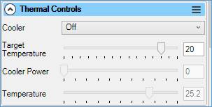
Cooler (on/off) |
Allows any cooler present on the camera to be turned on or off. If the cooler is turned on, then the cooling level may be controllable using one of the two controls listed below. |
|
Cooler Power |
Allows the percentage power that the cooler runs at to be set. |
|
Target Temperature |
The temperature that the camera will attempt to cool to (adjusting the cooler power automatically to achieve this temperature). |
Basler Camera Controls
Drivers and further information can be found at the Basler website.
Basler cameras may appear more than once in the Cameras menu:
SharpCap has three separate options for working with Basler Cameras:
1. (LX Mode) suffix – uses the camera's trigger functionality (if present) to take longer exposures than the camera would normally allow. Only use this mode if taking longer exposures than those available from the other two options.
2. No suffix – the old code to support Basler cameras. Some functions such as pre-processing and display controls available with other cameras will not be available. This option is deprecated and will be removed in a future version. Do not use this option unless having problems with the Experimental option (below).
3. (Alternate, Experimental) suffix – a newer implementation of the Basler camera that should have all the modern SharpCap features. This should be the preferred way of working with Basler cameras if long-exposure functionality is not required. This will become the default method of working with a Basler camera in a future version.
Basler Specific Controls
|
Capture Format and Area |
|
|
Colour Space |
Basler cameras use non-standard colour space names for RAW modes. · BayerBG8 – equivalent to RAW8 with BGGR Bayer pattern. · BayerRG12 – equivalent to RAW12 with RGGB Bayer pattern. · Bayer GB12Packed – equivalent to RAW12 with GBBR Bayer pattern. In packed 12 bit modes, 2 adjacent pixels are packed into 3 bytes (1.5 bytes each) rather than requiring 2 bytes each in unpacked mode. This may increase frame rates in some circumstances as it reduces the amount of data that needs to be transferred from the camera to the computer. |
|
FPS |
The number of frames per second that the camera will attempt to deliver to the computer. When left on auto it will aim for the maximum possible rate. Note that the frame rate set in manual mode may not actually be achieved due to factors such as the exposure being too long or the data rate between the camera and the computer being insufficient to cover the desired frame rate. If aiming for a limited frame rate, then setting this to a low value is better than leaving this at a high value and setting the 'Frame Rate Limit' control as it should reduce the CPU load on the capture computer. |
|
Camera Controls |
|
|
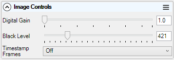
Black Level |
Allows the black level to be adjusted. This control should be adjusted with the camera covered to ensure that both sides of the black level peak in the histogram are visible and distinct from the zero level to ensure that black level noise can be averaged out correctly in stacking. Called offset or brightness on some other cameras. |
|
Digital Gain |
An additional gain that can be applied to the image. Each step above zero doubles the image brightness but also doubles the noise levels |
|
Processing Controls (should be Image controls for consistency with other cameras) |
|
|
Auto White Balance |
Automatically adjust the white balance of the image when the 'Adjust' button is pressed. |
|
White Bal (R) [Colour Modes only] |
Controls the relative intensity of the red channel of a colour image. |
|
White Bal (B) [Colour Modes only] |
Controls the relative intensity of the blue channel of a colour image. |
|
White Bal (G) [Colour Modes only] |
Controls the relative intensity of the green channel of a colour image. |
Celestron/Imaging Source Camera Controls
SharpCap should support all Celestron branded Skyris and NexImage cameras (manufactured by The Imaging Source) as well as Imaging Source branded DMK and DFK cameras.
Drivers and further information can be found at the Imaging Source website and the Celestron website.
|
Camera Controls |
|
|
Focus |
Controls the focus of the built-in camera lens (if available). |
|
Iris |
Controls the aperture of the built-in camera lens (if available). |
|
Pan, Tilt and Roll |
Physical controls to pan, tilt and roll the camera if it has motor drive to allow it to be controlled remotely. |
|
IR Cut Filter |
Turn on/off the IR cut filter on cameras equipped with a controllable filter. |
|
Image Controls |
|
|
Colour Enhancement |
Enhance colours in the image. |
|
Highlight Reduction |
Reduce the relative brightness of the highlights in the image. |
|
Denoise |
Apply a noise reduction filter to each frame (will also tend to reduce detail). |
|
Colour Enable |
Switch colour cameras between colour and monochrome mode. |
|
Sharpness |
Apply a sharpening filter to each frame to enhance detail (will also tend to increase noise). |
|
White Balance |
|
|
White Bal (R) |
Controls the relative intensity of the red channel of a colour image. |
|
White Bal (B) |
As for White Bal(R) above, but controls blue. |
|
White Bal (G) |
As for White Bal(R) and (B) above, but controls green channel. |
iNova Camera Controls
SharpCap supports a range of iNova cameras.
Drivers and further information can be found at the iNova website.
|
Camera Controls |
|
|
Black level |
In theory, the same as the black level control documented for other makes (copy from QHY?), in practice does nothing due to a bug in the iNova SDK. |
|
Pixel Clock |
How fast the internal CPU of the camera runs. Higher speeds can give higher frame rates but sometimes too high a speed will lead to no frames at all. |
|
Horizontal Blank |
How long a delay the camera should apply between reading one scan line of the image and the next. Usually best left on auto, but manual tweaking can sometimes improve frame rates, with lower values giving faster frame rates. As with many of these speed controls, going too far can cause the frame rate to collapse to zero. |
Point Grey Camera Controls
SharpCap supports FlyCapture based Point Grey cameras. Spinnaker based cameras are not supported. USB, GigE and Firewire models are all supported.
Drivers and further information can be found at the Point Grey website.
Note that you may need to restart SharpCap to detect GigE cameras if they are connected after SharpCap has been run.
|
Camera Controls |
|
|
Auto Exp Target |
This indicates the brightness that the Auto options for Exposure and Gain will aim for when enabled. Higher values (above zero) indicate brighter exposure, negative values indicate lower exposure. |
|
Actual Temperature |
This indicates the temperature of the senor in Celcius |
Depending on the colour space chosen (i.e. RAW, MONO or RGB), different Image Controls from the list below will be available.
|
Image Controls |
|
|
Digital Processing |
Turning this control on will enable the other image controls listed below but may reduce frame rate slightly. Turning this control off will disable the other image controls but ensure that image data viewed and saved will match the data read from the camera sensor without any processing in software. |
|
Gamma |
Adjusts the gamma of the image |
|
Brightness |
Adjusts the brightness of the image. Warning: This is not a simple Brightness control that merely adds a constant offset to the values of all pixels. The exact implementation of this control is unclear, but in RGB mode it appears to affect the relative strength of the colour channels. |
|
Sharpness |
Applies a simple sharpening to the image (note that this will also increase noise in a noisy image) |
|
Hue |
Adjusts the colour tint of the image |
|
Saturation |
Controls the strength of colour in an RGB image |
|
White Bal (Red) |
Controls the relative intensity of the red component of a colour image |
|
White Bal (Blue) |
Controls the relative intensity of the blue component of a colour image |
QHY Camera Controls
SharpCap supports a wide range of QHY CMOS cameras, including QHY5L-II, QHY5-III, QHY174, 178, 224, 290, 163 and 183. The cooling features of the QHY ColdMOS cameras are supported as well as the GPS features of the QHY174-GPS.
Drivers and further information can be found at the QHY website.
|
Camera Controls |
|
|
Amp Noise Reduction |
This control is available for some cameras and when activated will reduce the amount of amp glow created by the camera for long exposures.
In general, it is best to leave this control on the 'Auto' setting as it will apply the amp glow reduction when appropriate. If amp glow reduction is enabled manually, this may result in incorrect images for certain exposure and gain combinations. |
|
Row Noise Reduction |
This control is available for some cameras and can be adjusted to reduce banding effects between camera rows. |
|
Offset |
Allows the black level to be adjusted. This control should be adjusted with the camera covered to ensure that both sides of the black level peak in the histogram are visible and distinct from the zero level. This ensures that black level noise can be averaged out correctly in stacking. |
|
Speed |
Control the transfer speed being used by the camera. May increase frame rate in some circumstances. |
|
USB Traffic |
This controls how fast the camera will try to push data over the USB bus. Setting a lower value will try to move data faster and give higher frame rates. Setting a value that is too low can cause: · dropped frames · a collapse in frame rate · or even no frames at all |
|
Use DDR Buffer |
Available on some cameras. Turns on/off the use of the internal DDR buffer on the camera. Using the DDR buffer may improve frame rate and reduce problems with dropped frames. |
|
Optimize Light Level |
Allows the sensor on the camera to be optimized for low or bright light levels. |
|
Filter Wheel |
Allows a QHY filter wheel connected via the camera port to be controlled. Note that a connected filter wheel may not be detected if it is still initializing when the camera is opened in SharpCap. |
|
Enable Live Broadcast |
Enable live broadcast of the images being shown in SharpCap via the QHY video broadcast application. |
|
GPS Controls |
|
|
GPS |
Enable or disable the built-in GPS functionality on cameras that support it. The GPS feature allows frames to be timestamped precisely to microsecond precision. GPS may require the camera to be supplied with 12V power. When GPS is enabled and has a satellite lock the timestamp for each frame taken from the GPS system is used for the timestamp in capture settings files and SER file frame timestamps. Without further adjustment, frame times will be accurate to millisecond levels, but to get microsecond precision the following controls must be adjusted correctly. |
|
GPS Calibration LED |
The GPS calibration LED must be turned on to be able to correctly adjust the following two controls. The camera must also be covered so that the light from the LED can be seen in the image. Turn up the gain so that the light can be seen easily. |
|
Calibration Start Pos |
With the GPS LED on, turn the calibration Start Pos down to zero and then turn it up until the calibration light appears as a glow at one side of the image. Then turn the value down a small amount until the light vanishes again. Setting this control allows the GPS frame start time to be corrected for the time difference between the camera circuitry requesting the frame starts and the actual exposure starting. |
|
Calibration End Pos |
With the GPS LED on, set this to a value just above the calibration Start Pos value and then turn up the value until the LED light vanishes again. Turn the value down a small amount until the light re-appears. This allows the end of frame time to be adjusted for the time difference between the camera circuitry requesting the frame to stop and the frame having finished.
After calibrating the Start and End Pos, don't forget to turn the calibration LED off again. Also, note that the calibration needs to be repeated after having changed the camera exposure or the camera colour space. |
|
Image Controls |
|
|
White Bal (R) [Colour Modes only] |
Controls the relative intensity of the red channel of a colour image. |
|
White Bal (B) [Colour Modes only] |
As for White Bal(R) above, but controls blue.
|
|
White Bal (G) [Colour Modes only] |
As for White Bal(R) and (B) above, but controls green channel.
|
|
Thermal Controls |
|
|
Cooler Power |
Allows the percentage power that the cooler runs at to be set. If set to Auto, then the cooler will automatically attempt to cool the sensor to the temperature given by the Target Temperature control. |
|
Target Temperature |
Sets the sensor target temperature for use when the cooler power is set to Auto. |
Starlight Xpress Camera Controls
SharpCap supports the full range of Starligh tXpress CCD cameras. Drivers and further information can be found at the Starlight Xpress web site.
Capture Format and Area
Some Starlight Xpress cameras have interlaced sensors, meaning that only half of the lines on the sensor can be read at a time. When a camera with an interlaced sensor is in use, SharpCap adds an Interlace Handling control to allow various ways of dealing with the interlaced camera to be chosen.
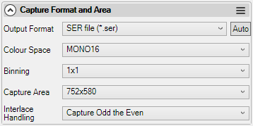
The options for Interlace Handling are
· Capture Odd then Even Rows - this option will expose the camera twice for each frame shown in SharpCap, first capturing the odd lines of the sensor, then the even. This is the only option that gives full sensor resolution, but frame rate is halved (for instance with a 2s exposure selected, the image will only update once every 4s)
· Interpolate from Odd Rows – this option will only expose the odd rows of the sensor, but will generate a full-size image by generating data for the even rows by averaging (interpolating) the data of the odd rows on either side. Frame rate will be normal, but there will be less detail in the image
· Interpolate from Even Rows – as Interpolate from Odd Rows, but exposes only the even rows of the sensor, with the odd rows being generated by averaging
· Capture Odd Rows – exposes the odd rows of the sensor and forms an image only half the normal height (290 pixels for the camera shown above). Frame rate will be normal, but images will be distorted due to halving the height of the image
· Capture Even Rows – as Capture Odd Rows, but captures only the even rows.
· Capture All Rows (2x vertical bin) – this option exposes all pixels on the sensor, with a 2x vertical binning being applied before reading the sensor. As for Capture Odd Rows and Capture Even Rows, the image will be distorted due to being half normal height, but the sensitivity of the sensor is maximised as all pixels are exposed and measured in each frame.
Image Controls
|
Image Controls |
|
|
Digital Gain |
Starlight Xpress CCD cameras do not have an analogue gain adjustment option, but the deep well depth means that a usable image can be generated even at relatively low saturation levels. Unfortunately, such images are very dark due to the signal on each pixel being low compared to the maximum signal. The digital gain option provides a way to compensate for this problem by boosting the whole image after it is read from the sensor, by a factor of up to 100x. The use of Digital Gain is particularly helpful when focussing or using the Polar Alignment tool.
|
|
Black Level |
This is a software black level adjustment. It should only be necessary to adjust this control when using the Digital Gain option (to keep the black level of the histogram down to a reasonable range).
|
ZWO Camera Controls
SharpCap supports the full range of ZWO cameras, including support for high resolution ASI1600 cameras and cooled cameras.
Drivers and further information can be found at the ZWO website.
Camera Controls
|
|
|
|
Camera Controls |
|
|
Turbo USB |
Controls how fast the camera will try to push data over the USB bus. Setting a higher value will try to move data faster and give higher frame rates, but setting a value too high can cause: · Dropped frames. · A collapse in frame rate. · Or even no frames at all. In general, leaving this setting on Auto will work well in most circumstances, but if there are issues with no frames, stuttering frames or low frame rates then try adjusting this option. |
|
High Speed Mode |
May improve the frame rate under some circumstances. Changes from using the 12bit ADC on the camera to using a 10bit ADC. Enabling high speed mode may increase image noise when the gain is set to a low value. |
|
Hardware Binning |
Only applies when binning is enabled. Calculates binning on the camera itself rather than in software in the camera driver. Increases gain and noise and increases frame rate. |
Image Controls
|
|
|
|
Image Controls |
|
|
White Bal (R) [Colour Modes only] |
Controls the relative intensity of the red channel of a colour image. Along with White Bal (B) this can be used to correct the white balance of an image. Note that setting either of the two ZWO white balance controls to auto sets them both to auto. |
|
White Bal (B) [Colour Modes only] |
As for White Bal(R) above, but controls blue. Note that there is no control for the green channel, but that isn't needed as the relative strength of the green channel can be increased or decreased by making the opposite change to both red and blue. |
|
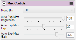
Mono Bin [Colour Cameras only] |
Only applies when binning is selected. Creates a monochrome binned image rather than a colour binned image. |
Thermal Controls
|
Thermal Controls |
|
|
Cooler On/Off |
Turns the camera cooler on or off. The camera must be connected to 12V power to allow the cooler to operate. |
|
Target Temperature |
The temperature the camera will try to achieve if the cooler is turned on. |
|
Cooler Power [Read only] |
The current power percentage that the cooler is running at. |
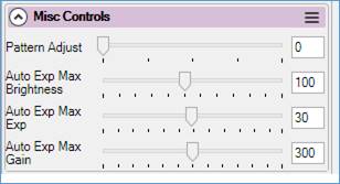
Miscellaneous Controls
|
These
control the auto exposure and auto gain functions of the
camera. |
|
|
Miscellaneous Controls |
|
|
Auto Exp Max Brightness |
Auto Exp Max Brightness sets the target level for the maximum brightness point in the histogram in the range 50 (targets a histogram peak at about the 20% level) to 150 (targets a histogram peak at about the 60% level). |
|
Auto Exp Max Exp |
Auto Exp Max Exp is the maximum exposure (in seconds) that can be used when auto exposure is enabled. |
|
Auto Exp Max Gain |
Sets the max allowable gain in the same way. |
DirectShow Cameras
Microsoft DirectShow is an architecture for streaming media on the Microsoft Windows platform.
There are a vast number of webcams and frame grabbers on the market. In general, SharpCap should work with any of them but some cameras/grabbers have buggy drivers which may prevent them from working correctly with SharpCap. The controls available in SharpCap are determined by the driver – SharpCap just shows the controls the driver makes available. Sometimes more controls are available in the Video Capture Pin and Video Capture Filter dialogs provided by the device driver.
Additionally, SharpCap allows the images being captured from a webcam to be processed by sophisticated features available to dedicated astro cam users – for instance Live Stacking and Polar Alignment are both usable with images coming from a webcam or frame grabber provided a long enough exposure can be set to start seeing details and/or stars.
Webcams
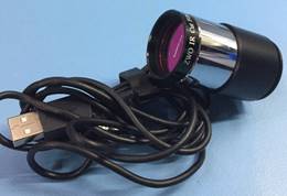
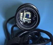
Many budget webcams usually need some adaptation to be used for imaging. This usually involves removal of lenses, auto-focusers (which includes the infra-red filter) and addition of a webcam 1.25” adapter and IR cut filter.
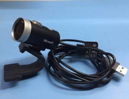
Microsoft LifeCam (webcam)
The Microsoft LifeCam HD is a common web cam which can be modified for astro use – it would typically be used for lunar/planetary image capture but not deep sky objects. Its capability can be seen in the Jupiter images at the SharpCap gallery .
These webcams can be found on eBay for around £15 and would need an IR cut filter (around £10 on eBay). Modification details can be found at http://dslrmodifications.com/lifecam/lifecam1.html, showing the camera being fitted into a disused or low cost telescope eyepiece.
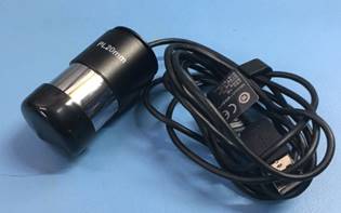
|
Original Microsoft LifeCam |
Modified and fitted into a 1.25” eyepiece |
|
Showing IR cut filter |
Sensor view |
When a Microsoft LifeCam is the active camera, additional menu Options appear in SharpCap.
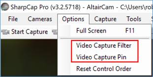
With the Microsoft LifeCam, the useful extra options are:
· Video Capture Filter
· Video Capture Pin
Video Capture Filter and Video Capture Pin are options which show setup dialogs created by the camera’s manufacturer. The Video Capture Filter dialog can also be accessed via the Camera Control Panel by pressing the ‘Show’ buttons next to the options control.
|
|
|
|
Video Capture Filter |
Video Capture Pin |
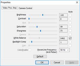
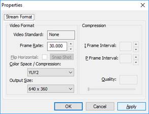
Note that the controls available in, and the design of, the Video Capture Filter and Video Capture Pin dialogs is determined by the camera driver for the camera being used, not by SharpCap.
Frame Grabbers
A frame grabber is an electronic device able to capture frames from an analogue video signal. The frame grabber is a USB device. The analogue video signal is commonly supplied by a day/night CCTV style security camera. This type of camera, generically called an astro video camera, is commonly based on the LN300 style CCTV body, usually with enhanced firmware or electronics which allow for internal stacking of video frames. Camera output can be to a frame grabber or an analogue screen. This arrangement is commonly used for live image display and internet video broadcasting of astronomical objects particularly in outreach type scenarios. This arrangement has proved to give satisfactory results under heavily light-polluted skies.
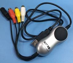
A typical video capture device is the EzGrabber from http://www.ezcap.tv/. [Note: there are lots of clone devices that look the same as the ezcap but may contain completely different hardware and have different drivers – sometimes these drivers have compatibility problems.]
Well known manufacturers of the astro video type cameras are Revolution Imager and Mallincam.
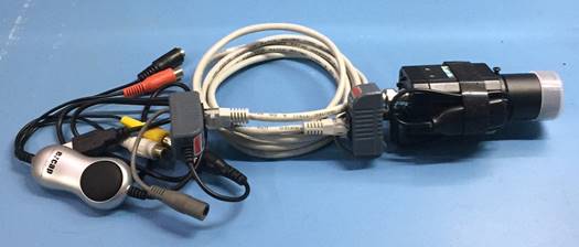
A typical setup comprising frame grabber and astro video camera is shown below.
|
Analogue video camera with Bluetooth adapter for accessing the camera’s internal menu. Video/power balun (left hand side) used to connect ethernet cable. |
USB2 video frame capture device. Shows in SharpCap as a USB 2861 device. |
|
From left to right – video frame grabber, balun, ethernet cable, balun, analogue video camera. |
|
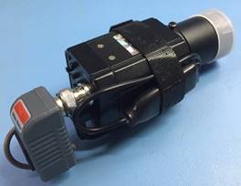
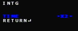
SharpCap will see this USB frame grabber as a USB 2861 (typically 28xx) device. The details of the camera connected to the frame grabbing device will not be detected by SharpCap. The camera is controlled by its own internal menu system and is usually accessed via a USB or Bluetooth connection. This type of camera typically has a maximum resolution of 720 x 576 and will be NTSC or PAL.
|
|
|
|
SharpCap view of a frame grabber |
Astro video camera internal menu |
Modified Webcams
Modified webcams are those which have been electronically modified. Typical modifications are long-exposure (LX) and amp glow removal. SharpCap 3.1 and above no longer support LX modified webcams - you should use an earlier version of SharpCap (3.0 or earlier) to control these cameras. Details on their use can be found in an earlier version of this user manual.
DirectShow Controls
DirectShow cameras have a fixed set of available controls defined by Microsoft, however not all cameras will offer all these controls.
|
Format & area (Video format) · Colour space · FPS · Resolution · Frame divisor |
Camera controls · Pan · Tilt · Roll · Zoom · Exposure · Iris · Focus |
Image controls · Brightness · Contrast · Hue · Saturation · Sharpness · Gamma · Color Enable · White Balance · Backlight Compensation · Gain |
Virtual Cameras
SharpCap can talk to a wide range of cameras directly and even more via either an ASCOM or DirectShow driver. It also has a pair of testing (simulated) cameras that can be used to try out the features of the program on cloudy nights. The Virtual Folder Monitor Camera adds another way to get images into SharpCap – it can read existing or newly added image files from a directory opening up new ways to use SharpCap. As a couple of examples:
· You have a camera that isn’t supported by SharpCap, even using a DirectShow or ASCOM driver, but you have an application that will capture frames from that camera and save them to a folder. You can use the folder monitor virtual camera to load each new frame saved to the folder into SharpCap, allowing you to access SharpCap tools like focus measurements, live stacking, etc.
· You have a series of image frames of a target captured with either SharpCap or another capture application. You can use the folder monitor virtual camera to live stack these frames in SharpCap (or repeat the live stacking with different parameters if these were frames originally saved in SharpCap).
The virtual folder monitor camera only has a limited set of controls available – it’s obviously not possible to adjust camera controls like exposure, gain or colour balance when the images are being read from saved files! The resolution and colour space values are also determined by the contents of the image files being loaded and cannot be changed.
You do have the ability to browse for the folder that contains the files you want to work with and move through the list of files in the folder either automatically (in play mode) or stepping forward/back manually in pause mode. Additionally, dark subtraction and flat frame correction can be applied and the frame rate limit can be set.
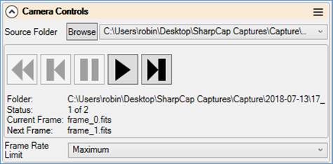
To select the folder source, press the ‘Browse’ button and either select a folder (which will process all image files in that folder) or select a single image file (PNG, TIF, FITS and JPG supported), which will process all image files of that type in the same folder. When you select a new folder:
· If the folder contains image files then the first image file of the selected file type is loaded into the camera and displayed, then the camera is paused automatically, allowing you to make any adjustments necessary or select tools such as live stacking before pressing the ‘Play’ button to begin processing the other images in the folder
· If the folder does not contain any image files then the camera will enter play mode automatically, which means that the first image will be processed and appear on screen soon after it is saved into the selected folder.
The playback controls (Rewind, Step back, pause, play, step forward) provide a way to move through the image files present in the folder.
Image files are always processed in date order (starting with the oldest first). The resolution and colour space values are selected from the first frame processed, and files that have different resolutions or colour space settings will be skipped. If SharpCap runs out of files in the folder (or if there are no image files in the folder initially) then it will wait for new image files to be added and load them when they appear.
If multiple image files are present in a folder and the ‘Play’ function is selected then they will be rapidly displayed in turn with no pause between images unless
· The frame rate limit control is set to limit the rate at which frames are displayed or
· Live Stacking is selected, in which case a new frame will be loaded only after the previous frame has completed any live stacking calculations, ensuring that no frames will be skipped by the live stacking.
The Virtual Folder Monitor Camera is a SharpCap Pro feature.
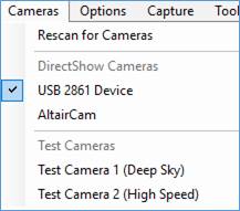
Test Cameras
The Test Cameras are useful to experiment with and understand settings and their effect. Much of the material in this manual has been derived from the Test Cameras. Hence this document can be used as a learning aid without having a telescope or camera attached to the PC/laptop or when the sky is cloudy. The use of a suitable lens (which can be purchased for a few pounds) will allow astro cameras to be tested without waiting for clear skies.
Test Camera 1 (Deep Sky)
See Common Camera Controls for a description of generic camera/image/display controls. [Note: some of the common controls currently have no effect, for example gain.]
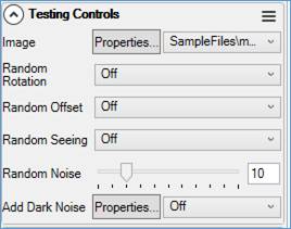
· Image – click the Properties button to load a PNG file stored in the SampleFiles folder. Other user created PNG, JPG or FITS files can be stored here for access via the test camera.
· Random Rotation – applies a random small rotation to each frame shown in the capture display area. On/Off, default = Off.
· Random Offset – applies a random offset effect to the image shown in the capture display area. On/Off, default = Off.
· Random Seeing – applies a random seeing effect to the image shown in the capture display area. The seeing effect is a blurring of the image. On/Off, default = Off.
· Random Noise(On/Off) – applies a random noise effect to the image shown in the capture display area. Default = 10, range 0..50.
· Add Dark Noise – will, by default, apply the file SampleFiles\1280x960x32RGB_dark.png to the image shown in the capture image. The image used for dark noise can be changed by pressing Properties – the image must be the same size as the main image.
Test Camera 2 (High Speed)
See Common Camera Controls for a description of generic camera/image/display controls. [Note: some of the common controls currently have no effect i.e. gain, exposure, gamma.]
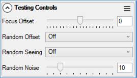
· Focus Offset – simulate focuser movement and can be used in Focus Score > Graph. Default = 0, range -10..+10. Note that this Focus Offset control is only available if the selected focuser in the Hardware Settings is set to None.
· Random Offset – applies a random offset effect to the image shown in the capture display area. On/Off, default = Off.
· Random Seeing – applies a random seeing effect to the image shown in the capture display area. The seeing effect is a blurring of the image. On/Off, default = Off.
· Random Noise – applies a random noise effect to the image shown in the capture display area. Default = 10, range 0..50.