Finding, Identifying and Framing Targets
SharpCap has a number of tools to help you find targets in the sky and get them positioned correctly in your camera’s field of view. While many of these tools require a GOTO mount to be set up in SharpCap, there is also assistance for users of non-GOTO mounts via the Push-To assistant tool.
Plate Solving
Plate Solving is the process of calculating the co-ordinates of an astronomical image by matching the patterns of stars seen in the image against a database containing information on the positions and brightness of stars in the sky. Many tools described in this section of the documentation either require Plate Solving in order to work or have enhanced functionality if Plate Solving is available.
While SharpCap has a built-in plate solving tool that is used for Polar Alignment, this tool is limited to working only in the areas of sky close to one of the north or south celestial poles. However, there are a number of freely downloadable Plate Solving applications that can be installed and SharpCap can be configured to use those applications for plate solving.
The applications that SharpCap can work with are:
· Astrotortilla (https://sourceforge.net/p/astrotortilla/home/Home/)
· All Sky Plate Solver - ASPS (https://www.astrogb.com/astrogb/All_Sky_Plate_Solver.html)
· Ansvr (https://adgsoftware.com/ansvr/)
· Astap (https://www.hnsky.org/astap.htm)
· PlateSolve2 (https://planewave.com/download/platesolve2/)
· PlateSolve3 (download link available via NINA documentation - https://nighttime-imaging.eu/docs/master/site/advanced/platesolving/)
To enable plate solving in SharpCap, you must:
· Install one of the tools above
· Install the appropriate database index files (star data) for the tool you have installed. The documentation or installer for your selected tool will explain how to do this
· Configure SharpCap to use the plate solving tool you have installed via the Plate Solving Settings
Once these steps have been completed, SharpCap will detect that a plate solving tool is available and the functionality that depends on plate solving will become enabled for use.
Note that plate solving an image can take a long time, especially for an image with a small field of view (possibly several minutes). The process can be speeded up if SharpCap can give hints to the plate solving application to reduce the amount of searching needed. SharpCap can send two hints to plate solving applications :
· The approximate position of the image in the sky – this is used if a GOTO mount is connected in SharpCap – the current co-ordinates of the mount are used as the approximate position, which forms the starting point of the search. In some cases SharpCap may limit the search area to within 15 degrees distance of the GOTO mount co-ordinates.
· The approximate size of the image (field of view). This is used if the pixel size of your camera is available and the focal length of your telescope has been configured in the Plate Solving Settings. Note that setting an incorrect focal length will lead to an incorrectly calculated field of view, which may cause plate solving to fail repeatedly. Set the focal length setting to Do not Use in case of uncertainty – plate solving will be slower but this possible cause of failure will be eliminated.
SharpCap will display notifications when plate solving using an external application begins and when it succeeds or fails.
If you have problems getting plate solving to work, the first thing to do is to check that sufficient stars are visible in the image – turn off the Display Histogram Stretch temporarily, since that can make stars visible on the display that are actually very faint. Plate solving tends to work best when between 100 and 300 stars are detected in the image by the plate solving application. If plate solving still fails after ensuring that stars are visible, check the SharpCap Log where additional information directly from the plate solving tool in use will be recorded. This information may help you work out what is going wrong.
Using Plate Solving in SharpCap
A number of SharpCap’s features will use plate solving automatically, but there are also two ways to launch plate solving directly from the Tools menu.
Plate Solve (Solve only)
This option is available provided that a supported plate solving application has been installed and configured for use in SharpCap. Selecting this option will cause SharpCap to perform the following actions:
· Capture a frame from the camera
· Pass the captured image to the configured plate solving application
· Request that the plate solving application search the whole sky
· Use the co-ordinates of a connected ASCOM mount as a starting point for the search. If no mount is connected but SharpCap knows the latitude and longitude then the point currently at the zenith is used as the starting point
· Wait for the plate solving application to complete its search
If plate solving succeeds, SharpCap will show a notification giving details on the co-ordinates, field of view and rotation of the current image, as shown below. The Copy button can be used to copy the plate solving details to the clipboard in text format.
![]()
SharpCap will also record the plate solving information internally, allowing it to be used if some other SharpCap functions requiring plate solving information are used immediately afterwards.
Note that SharpCap takes no further action with the plate solving results when this tool is used.
Plate Solve and Resync
This tool is available if a GOTO mount is configured and connected in SharpCap (in addition to a plate solving application having been installed and configured). Selecting this option will cause SharpCap to use plate solving to correct for any pointing inaccuracy of your GOTO mount, placing the target that you wish to view in the centre of the camera image.
The normal way to use this tool is to use the normal GOTO functions of your telescope mount to move it to the co-ordinates of the target you wish to view (you can use the handset, or a planetarium application or other tools in SharpCap to make choose the target and GOTO the target co-ordinates). Due to inaccuracies in the alignment or movement of the GOTO mount, the target may be off-centre or even out of view. At this point, use the Plate Solve and Resync tool and wait for the procedure to complete – if it is successful then the target should be centered in view.
In more detail, the tool performs the following actions:
· Capture a frame from the camera
· Pass the captured image to the configured plate solving application
· Store the current co-ordinates from the ASCOM mount as the target co-ordinates
· Use the co-ordinates of a connected ASCOM mount as a starting point for the search
· Request that the plate solving application search within 15 degrees distance of the starting point
· Wait for the plate solving application to complete its search
· Move the mount to place the target co-ordinates in the center of the camera view.
The last stage may be done either by using a ‘Sync’ command to set the mount co-ordinates accurately followed by a GOTO, or by using a calculated offset GOTO. See the Plate Solving Settings for more information on this and which option to choose.
Note that this tool can also be launched by
using the GPS button (![]() )in the
telescope control area.
)in the
telescope control area.
Deep Sky Image Annotation
Deep Sky Image Annotation will label bright stars and deep sky objects in the image for you, making identification easy. It can be launched from the Tools menu provided that a plate solving application has been installed and configured for use in SharpCap. If SharpCap already has plate solving information stored (for example you have recently used Plate Solve Only or Plate Solve and Resync) then you will immediately see information about stars and deep sky targets overlaid on the camera image, otherwise SharpCap will prompt you to let you know that you need to plate solve.
If plate solving is required, it can be started by either double-clicking the image as prompted or using one of the two plate solve buttons in the Deep Sky Annotation Results window. Once plate solving completes successfully, SharpCap will show information on deep sky targets in view overlaid on the image.
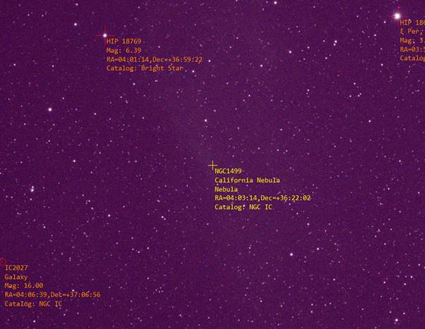
Additionally, the Deep Sky Annotation Results window shows when this tool is active, giving more information on the targets in view, information on targets nearby and options to customize the display and behaviour of the annotation tool.
On the Objects in View and Objects Nearby tabs you can select individual objects in the list to show their details in the right hand panel (for Objects in View, the selected object is also drawn in yellow rather than orange text). You can also set the target name (used for file naming when capturing) to the name of the selected object and SharpCap can automatically center any object in view if you have a GOTO mount connected.
Closing the Deep Sky Annotation Results window will turn the annotation off.
Saving the annotated image
You can save the image with the annotations added by using the Save Image With Annotations button at the bottom right of the results window. The image will be saved into PNG format and the text will be sized for viewing at 100% zoom.
Plate Solving for Image Annotation
Image annotation requires accurate plate solving information. If you are using a GOTO mount in SharpCap then the software can compensate for small movements of a few degrees from the position where the plate solving was originally carried out. If you are not using a GOTO mount in SharpCap then you must perform a new plate solve each time you move the mount, otherwise the annotation markings will be shown in the wrong positions on the image.
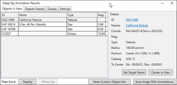
Plate solving operations can be launched using the two buttons in the Annotation Results window.
![]()
The two buttons operate as follows:
· Nearby – solves within 15 degrees of the current GOTO mount position or the most recent plate solve result position (if no GOTO mount connected). Always available when a GOTO mount is connected, available for 2nd and subsequent uses when no GOTO mount.
· Whole Sky – attempts to find a solution across the whole sky, so may take longer. Not available if a GOTO mount is connected.
If you are imaging near the north or south celestial poles then the errors in object positions may be larger than usual (particularly if the pole itself is inside the field of view). To minimise errors, plate solve again when moving the mount at all if near the pole.
Configuring Image Annotation Settings
On the Display tab, you can configure which types of object should be shown, which catalogs to use and what information on each object should be shown on screen. It is also possible to customize the font size and the size of the marker cross used for point objects.
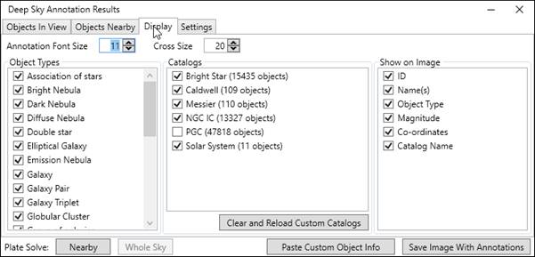
Any catalogs or object types that are unticked will not be shown on the image or in the Objects In View/Nearby lists.
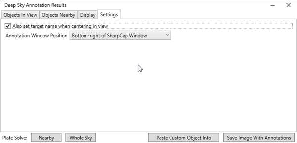
Finally, there are a small number of settings that can be configured on the Settings tab.
Custom Catalogs and Objects
SharpCap includes 5 built-in catalogs:
· 110 Messier objects
· 109 Caldwell objects
· 13327 NGC/IC catalog objects
· 15435 Bright stars (down to magnitude 7)
· 11 Solar System objects (Sun, Moon, 8 Planets, Pluto – positions calculated in real time)
These catalogs provide good coverage of the most common deep sky imaging targets, but some people will want to add more specialist objects to SharpCap’s catalogs (for instance variable stars, planetary nebulae, etc). This can be achieved in two ways – custom catalogs and pasting custom object information.
Custom catalogs are suitable when you want to add a large number of objects or you want the same objects to appear in SharpCap every time you launch it. Pasting custom object information is suitable when you only want to add a single object (or a small number) and you only intend to use the information once – this might be good for adding a comet or asteroid.
Note that custom catalog data is not only used by SharpCap in Deep Sky Image Annotation – objects in custom catalogs can also be selected for tools such as Goto Catalog Target and the Push-To Assistant.
Note that using custom catalogs is a SharpCap Pro feature. If you do not have a SharpCap Pro license, SharpCap will simply ignore any custom catalog files.
Custom Catalog File Format
The format for custom catalog information is text in the following format
IDs|Names|Type|RA(decimal hours)|Dec(degrees)|VMag|RMax(arcmin)|RMin(arcmin)|PosAngle
IC0001|IC0001|Double star|0.14084722|27.717667||||
IC0002|IC0002|Galaxy|0.18357778|-12.822861||0.98|0.32|142
The fields in each row are separated by the vertical bar character (|), and are – in order :
· ID or IDs of the object
· Name or names of the object (may duplicate the ID if no common names)
· Object type
· Declination in decimal degrees
· Right Ascension in decimal hours (0 to 24)
· Visual Magnitude (optional)
· Maximum radius in arc minutes (optional)
· Minimum radius in arc minutes (optional)
· Position angle of elliptical extent (0 is N/S, 90 is E/W, etc) if RMax > RMin (optional)
Note the following:
· All numeric values must use ‘.’ for the decimal separator, not a comma.
· The first three fields may contain any characters except the vertical bar separator character.
· Multiple IDs or Names should be separated by a comma – i.e. ‘NGC1976,M42|Great Orion Nebula, Orion Nebula|…’
· The last three fields specify the size of extended objects – only RMax is required for a circular extent, RMax, RMin and PosAngle are required for an elliptical extent
· The header row is not required
Text in this format can be pasted from the clipboard using the Paste Custom Object Info button – this will add the custom objects to SharpCap’s catalog – they will be available until SharpCap is closed but will not be available the next time you run SharpCap.
Custom catalog files should be text in this format and should be saved as a CSV file into the folder (the AnnotationCatalogs sub-folder does not exist by default and must be created):
C:\Users\<your user name>\AppData\Roaming\SharpCap\AnnotationCatalogs
Note that custom catalogs and pasting custom object info are both SharpCap Pro features and you will need a SharpCap Pro license to use them.
Goto Catalog Target/Co-ordinates
The Goto Catalog Target/Co-ordinates tool is available if a GOTO mount is configured and connected in SharpCap. Enhanced functionality is available if you have a plate solving application configured. If you use a non-GOTO mount, consider using the Push-To Assistant instead.
When this tool is launched from the Tools menu, the Goto Catalog Target/Co-ordinates window will appear, which allows you to choose the target and set a variety of options controlling how the GOTO process will proceed. The list of steps that SharpCap will carry out is shown at the bottom of the window.
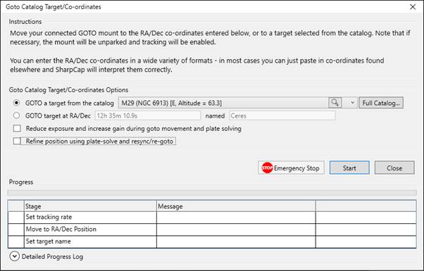
The operation of this tool is simple:
1) Select a target either from the catalog or by entering co-ordinates (see Choosing a Target, Choosing a Target from the full Catalog, Entering Target Co-ordinates Manually)
2) Set options for additional steps to be performed such as using plate solving to refine the final position (see Setting Options for the GOTO movement)
3) Press the Start button
The progress of the operation will be shown as the GOTO movement and any other steps complete. At any time during the procedure the Cancel button can be used to stop the process or the Emergency Stop button can be used to stop the process and immediately stop the GOTO movement if necessary.
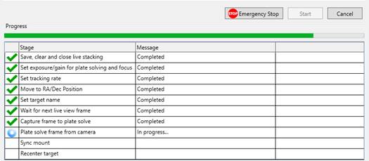
Once the process is complete, the window itself will close automatically a few seconds later.
Choosing a Target
The quickest way to choose a target is to pick one from the dropdown short catalog list – this contains the targets from the Messier and Caldwell catalogs, along with the 10 solar system targets. The list is ordered by current altitude with those targets highest in the sky first and those lowest (or below the horizon) last. SharpCap also indicates the compass direction of each target so that you can take into account any limitations of your observing location (i.e. if you have poor viewing to the north due to nearby trees).
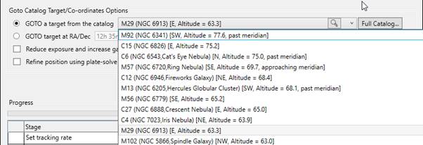
You can also use the search button to the right of the drop down and enter a catalog ID such as M42 or part of a target name. SharpCap will show the objects in the short catalog that match the search text that you enter
![]()
Of course, the short catalog is rather limited with just the 219 objects of the Messier and Caldwell catalogs available to choose from. A much wider range of objects (and a powerful method to filter and sort the available objects) is available by pressing the Full Catalog… button.
Selecting the Sun as a GOTO Target
IMPORTANT WARNING – VIEWING THE SUN THROUGH A TELESCOPE CAN LEAD TO BLINDNESS
Pointing a telescope at the Sun without using proper filters to cut down the amount of light can be extremely dangerous. Looking through a telescope at the sun without proper filters will almost certainly lead to instant, permanent, blindness. Cameras or other equipment connected to a telescope pointing at the sun are likely to be damaged. The telescope itself may be damaged if concentrated sunlight cracks mirrors or lenses, or melts plastic parts.
SharpCap will warn you if you ask it to move the telescope to point at the sun by selecting the ‘Sun’ target from the catalog or using other tools or sequencer steps to move to that target.
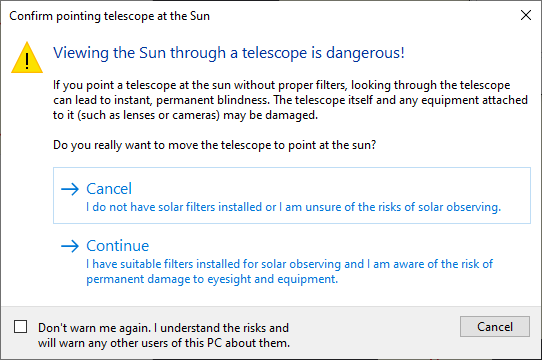
If you have suitable filters installed that will protect the telescope, camera and your eyes then you can choose to Continue. If you do not have proper filters installed, or you are unsure, choose Cancel.
To avoid this warning from becoming annoying for people who regularly observe the sun, it is possible to permanently disable it by ticking the Don’t warn me again… check box at the bottom. Please remember that if other people use this computer, they need to be aware of the dangers of pointing the telescope at the sun, as the warning will not show for them.
IMPORTANT NOTE: SharpCap cannot prevent you from pointing a telescope at the sun in all circumstances. If you enter co-ordinates manually that are close to the sun then you will not see this warning box. If your mount is misaligned then the telescope may end up pointing at the sun even when the co-ordinates of the mount indicate it is pointing elsewhere. If you use your telescope during the day then you need to be aware of the risks of the telescope pointing at the sun.
Choosing a Target from the Full Catalog
Pressing the Full Catalog… button launches the Select a Target window, which will appear as shown below.
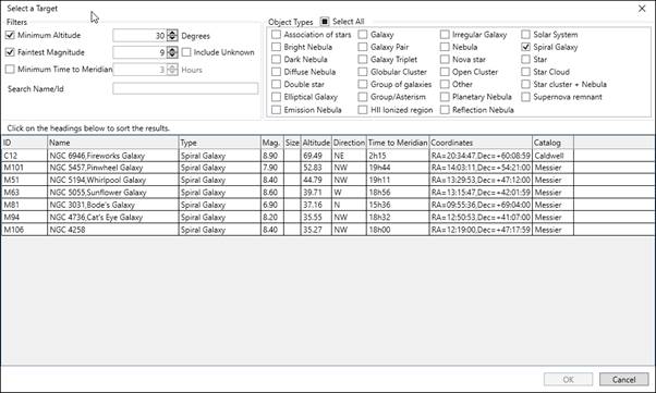
The window is divided into three areas
· The filter area in the top left – here you can choose to filter the targets according to the following conditions
o Only include targets above a selectable minimum altitude – this helps exclude targets that are close to the horizon and will give poor views or be blocked by trees or buildings
o Only include targets down to a selectable faintest magnitude. Note that the catalogs include many deep sky targets that do not have a magnitude value, so targets with no magnitude can be included or excluded
o Only include targets that have at least the specified time before they cross the meridian – this helps exclude targets which will require a meridian flip imminently
o By name – enter part or all of a target name or ID to filter the list to only those targets matching the text.
· The object type selection in the top right – here you can choose which types of object you are interested in by ticking or unticking the various types. You can use the Select All checkbox to quickly tick or untick all object types.
· The Results List at the bottom which shows the targets matching the criteria you have selected.
By default, the objects listed in the result list are ordered with the ones with the highest current altitude (nearest the zenith) first and the lowest altitude last. However, by clicking on the headers of the list you can sort the list by other criteria such as magnitude or time to meridian.
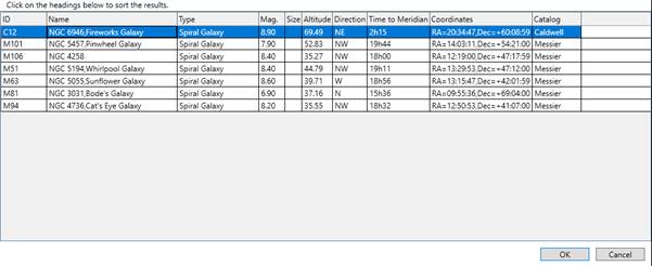
Once you have found the target that you wish to move the telescope to, click on it in the Results List then press the OK button – the selected target will be transferred to the main Goto Catalog Target/Co-ordinates Window.
![]()
Note that SharpCap will remember the settings for the various filters and the object types to be included for the next time you use the Select a Target window. Custom Catalog objects will appear in the results in the Select a Target window but not in the short catalog dropdown.
Entering Target Co-ordinates manually
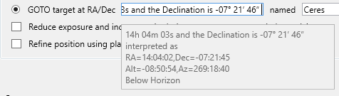
If you wish to move to a target that is not in any catalog – perhaps one that moves like a minor planet or comet – you can enter the co-ordinates manually. Select the GOTO target at RA/Dec option and enter the co-ordinates and optionally an object name.
SharpCap will interpret most formats for celestial co-ordinates and will ignore text around them as long as the only numbers are the co-ordinates and the RA comes first before the Dec. For instance, on a popular night sky website, the following text was found describing the current position of Asteroid 1 Ceres
The current Right Ascension of Dwarf Planet 1 Ceres is 14h 04m 03s and the Declination is -07° 21’ 46”
As long as the ‘1’ of ‘1 Ceres’ is not included, it’s possible to paste the text ‘14h 04m 03s and the Declination is -07° 21’ 46”’ directly into the target co-ordinates box and SharpCap will interpret it correctly. SharpCap shows a popup giving details of how it has interpreted the co-ordinates, which also includes the calculated altitude and azimuth of the target (here it is sadly below the horizon!).
Setting Options for the GOTO movement
There are three options that may be available to configure the GOTO process as shown below

Reduce exposure and increase gain during goto movement and plate solving
This option is available when the camera exposure is set to more than 5s, the camera also has an adjustable numeric gain control and both exposure and gain are in manual (not automatic mode).
When enabled, SharpCap will reduce the exposure during the main movement stage and during the plate solving/re-centering stage (if selected). Along with the exposure reduction to about 4s, SharpCap will increase the camera gain to compensate for the reduced image brightness caused by shorter exposures. At the end of the GOTO process, SharpCap will restore the original camera settings.
This option is particularly useful when longer exposures are in use – without the reduction in exposure, SharpCap may have to wait a long time for a new exposure to be available for plate solving, since it will ignore any exposure that was partly captured during mount movement.
Refine position using plate solve and resync/re-goto
This option is available as long as a plate solving application has been installed and configured for use in SharpCap.
When this option is enabled, SharpCap will automatically perform a Plate Solve and Resync operation after the initial GOTO is completed, ensuring that the selected target is placed into the center of the camera image.
Start a new Live Stack
This option is available if you are Live Stacking when you start the Goto Catalog Target/Co-ordinates process.
Regardless of whether this option is enabled or not, SharpCap will save and close the current live stack before the GOTO operation commences. This ensures that data from the live stack that is already in progress is not lost.
If this option is enabled, SharpCap will automatically start a new live stack after the GOTO operation is completed. Since the GOTO operation will set a new target name if one is specified, the new stack will be created with files named for the new target.
Goto Image
The Goto Image tool provides similar functionality to the Goto Catalog Target/Co-ordinates tool, but instead of choosing a target from the catalog or entering co-ordinates, you select a previously captured image of the target that you wish to return to.
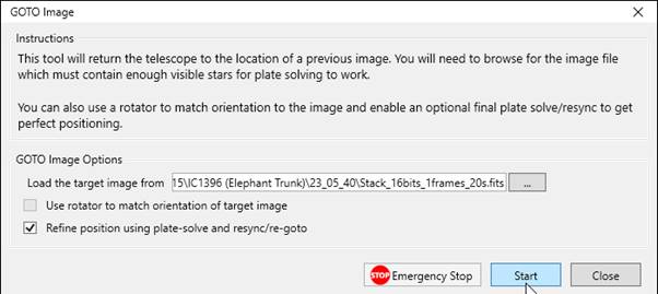
Press the ‘…’ button to browse for an image – you can use images in any format that SharpCap will write (PNG, TIFF, FITS or even JPG). You can select options to use a rotator device if you have one configured in SharpCap to match the orientation of the camera to that of the image and also to refine the final position using plate solving.
When Start is pressed, SharpCap will work through a series of steps to carry out the action, including plate solving the target image to get the correct co-ordinates to move to. Since FITS images contain the co-ordinates of the mount used when capturing, selecting a FITS image as the target image should make this plate solving of the image stage fast.
As for the Goto Catalog Target/Co-ordinates tool, progress is shown at the bottom of the window, with each stage being ticked off as it is completed.
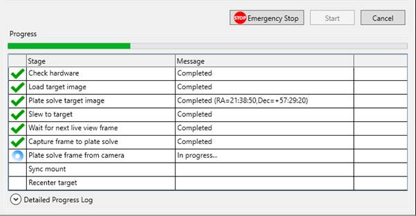
The Cancel and Emergency Stop buttons can be used to stop the process if necessary, with the Emergency Stop button additionally bringing all hardware movements to a halt.
Push-To Assistant
The Push-To Assistant provides target finding assistance for non-GOTO mounts using plate solving information to work out which direction (and how far) the mount needs to be moved to bring the target into view. Note that the Push-To Assistant is a SharpCap Pro feature.
This tool is available provided that a camera is open and is in Live View mode, and that a plate solving application has been installed and configured for use in SharpCap.
Since this tool relies on plate solving images, it is important to make sure that the image is well focused and the exposure and gain controls of the camera are set to ensure that plenty of stars are visible in each frame. A good starting point would be to set an exposure of 2s to 4s and a relatively high gain.
When the tool is selected, the Push-To Assistant window appears.
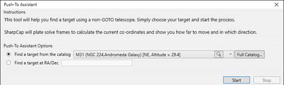
The top half of the window contains options for selecting the target object that you wish to find. These allow selection of the target from a catalog or entry of the target co-ordinates, exactly as for the Goto Catalog Target/Co-ordinates tool. See Choosing a Target, Choosing a Target from the Full Catalog and Entering Target Co-ordinates Manually for information on how using these features.
Once the target has been selected, press the Start button. This will cause SharpCap to start plate solving frames from the camera – the current plate solving status and the movement needed to get the telescope to the target will show in the lower part of the Push-To Assistant window. Initially the movements will be Not yet known – this will update when the first attempt at plate solving succeeds.
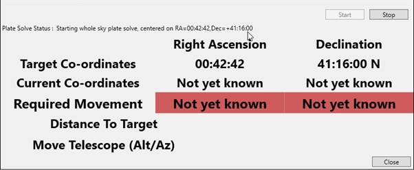
Once some plate solving information is available, SharpCap will display the movements required to reach the target.
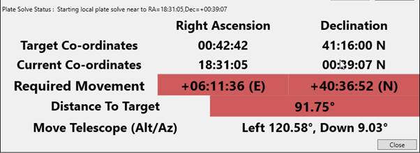
The Required Movement line in the information gives the movements required in RA/Dec to reach the target. If you are using an Alt/Az mount, then follow the instructions in the bottom line instead.
Once you get closer to the target, the highlight colour for the Required Movement and Distance To Target rows will change from red (far away) through orange, yellow and finally green as you get very close to the target.
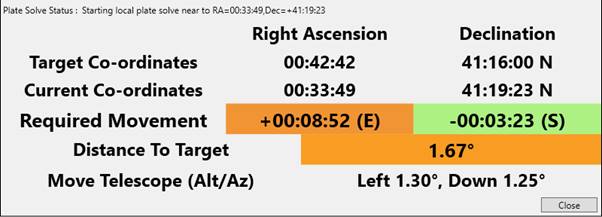
When you have located the target to the required degree of accuracy (an arc minute will usually be good enough) then you can close the Push-To Assistant window and begin imaging.
Push-To plate solving details
The first plate solve may be slow, as SharpCap will cause the plate solving application to check the whole sky for a result. However, once SharpCap has one set of results, it will use that position as the starting point for solving the next frame (with a 15 degree search limit), meaning that subsequent plate solving operations will be much faster.
SharpCap will continue to try plate solving based on the most recent location and a 15 degree search radius unless there are three failed attempts in a row – if that happens then SharpCap will revert to allowing the plate solving application to search the whole sky (although it will still use the last known position as the starting point). This will happen if you move the telescope a long way (more than 15 degrees) without pausing to allow a plate solve to complete.
Advanced Options using a virtual ASCOM telescope mount driver
Some additional options are available if you have an ASCOM mount driver connected in SharpCap – these are aimed at advanced users who use a virtual ASCOM mount driver such as the ‘Telescope Simulator for .NET’ to allow SharpCap and other applications such as Stellarium to share co-ordinates.
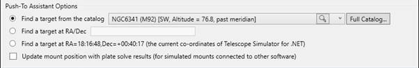
These options provide the following possibilities
Find a target at <Co-ordinates> (the current co-ordinates of <Name of ASCOM Mount Driver>) – If you have previously found the target you wish to view in a planetarium application such as Stellarium or Cartes-du-Ciel then SharpCap can use the co-ordinates that the other application has set for the telescope mount driver as the target.
Update mount position with plate solve results – when selected, SharpCap will update the position of the ASCOM telescope mount driver each time a plate solving operation succeeds. This means that if planetarium application is tracking the same ASCOM telescope mount driver, the planetarium application will automatically update to reflect the current pointing position of the telescope.
Pixel Position/Click to Recentre
The Pixel Position/Click to Recentre tool provides an easy-to-use way to see the celestial location of any part of the image and also a way to re-centre the image with on any selected point. In order to use this functionality, you must have a GOTO mount configured and connected to SharpCap. and have a plate-solving tool configured for use in SharpCap. If these conditions are not satisfied then the menu item for this tool will not be enabled.
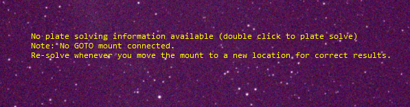
If you have already performed a plate solving operation recently (within a few degrees of the current position) then you will immediately see the direction rose display (see below). Otherwise you will see a crosshair with an information message stating that No Plate Solving information available.
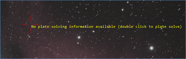
At this point you must perform a plate solving operation to enable the functionality of this tool. You can:
· Double click as prompted anywhere in the image. This will perform a plate solve operation limited to an area within 15 degrees of the current mount pointing co-ordinates.
· Use the Plate Solve and Resync menu item or the GPS button in the mount controls. These options will perform a plate solving operation as above and also resynchronize and recentre the mount around the original target co-ordinates – see Plate Solve and Resync for more information.
· Use the Plate Solve (Solve Only) menu item to perform a plate solving operation. Note that this scans the whole sky for a valid solution and will therefore frequently be a lot slower than the above two options.
One a plate solving operation has been completed successfully, the display will change to show the co-ordinates of the crosshair point and the direction rose overlaid on the camera image:
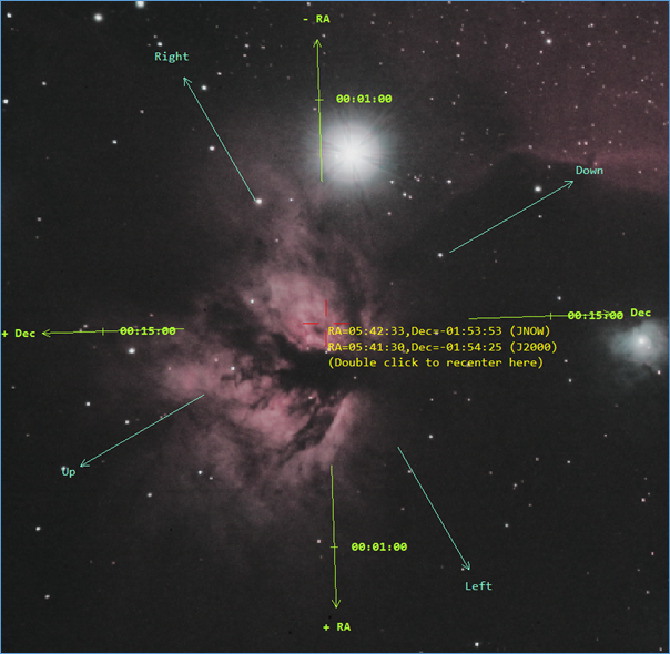
A great deal of information is present in this overlay:
· The red crosshair shows the selected point in the image. You can move this point by clicking anywhere in the image.
· The yellow text shows the RA and Dec co-ordinates of the selected point. Both the JNOW and J2000 values for the co-ordinates are shown. If you are using these co-ordinates to identify a feature against a star atlas, you will most likely need to use the J2000 co-ordinate values.
· The green arrows show the directions of increasing and decreasing RA and Declination within the image. For instance +RA points in the direction of increasing RA and -Dec points in the direction of decreasing declination
· The tick marks on the green arrows show the size of the change in RA and Declination from the reference point (the red crosshair) to the tick marks. For instance, above you can see the tick marks are at 15 minutes of arc in the + and – declination directions and 1 minute of RA.
· The cyan arrows show the orientation of the image in terms of the directions that would apply to a naked eye observer looking at the target – i.e. Down points towards the horizon, Up towards the zenith, left in the direction of reducing Azimuth co-ordinate, right in the direction of increasing Azimuth co-ordinate.
Once the direction rose is visible, you can recentre it on any part of the image by clicking on the target area.
Double clicking on the image activates the recentre functionality – SharpCap will calculate the mount co-ordinates that need to be set to put the point that was selected in the middle of the image – the calculations take account of any inaccuracy in the mount’s pointing that were detected by the plate solving and any movements since the plate solving operation.
When you double-click on a point, SharpCap
will prompt you to confirm the action : 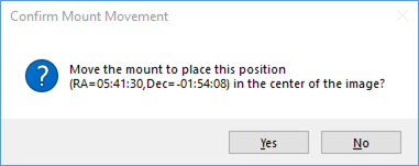
If you click Yes then the movement will take place, otherwise no action will be taken. Note that double-clicking to recenter is a SharpCap Pro feature.
Some actions will invalidate the plate solving information – this will cause the direction rose to no longer be shown. If this happens then perform another plate solving operation to re-enable the direction rose. Some of the actions that will cause this to happen include :
· Changing the resolution, binning or pan/tilt (ROI) settings of the camera
· Moving more than 10 degrees away from the mount position where the plate solving occurred.
You can disable the Pixel Position/Click to Recentre tool by selecting it again from the Tools menu.
Note that selecting this tool will disable any reticule that is currently visible and conversely, selecting a reticule will disable this tool.
Note: The RA and Dec arrows may point in incorrect directions and click-to-recentre operation may be inaccurate very close to the celestial pole – particularly if the celestial pole is within the field of view of the camera.
Note: The Up/Down/Left/Right arrows may point in incorrect directions very close to the zenith – particularly if the zenith is within the field of view of the camera.
Ghosted Image Alignment
The Ghosted Image Alignment tool provides assistance when manually trying to return the telescope to the exact position of a previously taken image by allowing the current image from the telescope and a previous reference image to be overlaid in the image display area. Any shift between the two will be visible as double stars, etc., allowing corrections to be made to align the two perfectly. The tool can also be used for manual mosaic creation, as the reference image can be offset by 75% of its width/height in any of the four directions.
If you use a GOTO mount, the GOTO Image tool may be easier to use for returning to the location of a previous deep sky image and the Lunar and Solar Mosaic Planners may be a better choice for mosaic images of the moon or sun.
When the Ghosted Image Alignment tool is selected, the work area will show controls to allow the reference image to be selected and adjustments to be made.
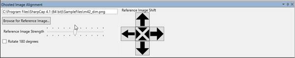
Browse for Reference Image – press this button to select the image file that SharpCap should use as the reference image. This file can be in any image supported by SharpCap (FITS, TIF, PNG, JPEG). Once you have chosen a reference image, the name and location of the reference image will be shown above the Browse button. The selected reference image needs to be the same size (width and height in pixels) as the camera image – if it is not then an error will be shown and the reference image will not be loaded.
Reference Image Strength – this slider allows you to adjust the relative strengths of the camera image and the reference image on the display. When set all the way to the left, only the camera image will be shown; when set all the way to the right, only the reference image will be shown; when set in the center (the default), the reference and camera images will have 50% strength each and will be seen overlaying each other, as shown below.
Rotate 180 degrees – when this box is checked, the reference image will be rotated through 180 degrees, which is useful after a meridian flip, since the movements of the flip will rotate the camera image through 180 degrees.
Reference Image Shift – these buttons allow you to shift the reference image by 75% of its width left or right, or to shift it by 75% of height up or down. This functionality allows a manually aligned mosaic to be captured more easily, since it helps ensure a consistent overlap between panels. If a direction shift is selected by pressing on of the direction buttons then the arrow on that button will highlight red until a different shift is selected or the shift is cancelled by pressing the center button.
Solar/Lunar Framing Assistant (Experimental)
This tool can assist with moving the field of view around on the solar or lunar disc using a GOTO mount. Often this sort of adjustment to move a different part of the disc into view can be a case of trial-and-error, since the camera view is usually rotated relative to the telescope movement axes, meaning that moving the mount east might well result in the image on screen moving perhaps down and to the left.
The Solar/Lunar Framing Assistant makes this easier by allowing SharpCap to work out how the image moves for each direction that the mount moves in a simple alignment procedure. After alignment is complete, you can use the mouse to drag the image around on-screen and SharpCap will move the mount to make the image move to match your requests. Note that the Solar/Lunar Framing Assistant is a SharpCap Pro feature.
When selected, you will see a small window showing the options for the tool and an overlay on the image which gives instructions on how to calibrate.
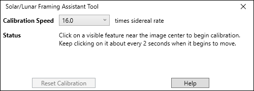
![]()
Calibration
The calibration procedure is very simply – just click on a recognizable point somewhere near the center of the camera image (it’s probably best to set the Zoom level to Auto before calibrating), and continuing clicking on the same feature in the image every couple of seconds as SharpCap automatically moves the mount first in one axis and then in the other.
If the movement of the target is too fast then you can try again after setting the Calibration Speed to a lower value. If the movement is very slow then increase the Calibration Speed instead.
During the calibration process, the overlay on screen will update to keep you informed about how far through the process you are:
![]()
Once the first axis calibration is complete, SharpCap will pause, waiting for you to begin the calibration of the second axis by clicking a feature on screen – if you need to, you can use a different feature for the second axis.
Calibration can fail for various reasons, including:
· A gap of more than 5s between clicks on the moving point during calibration
· Not enough click points during the movement – there must be at least 4 points in the final 80% of the movement distance (the first 20% of movement distance is ignored to deal with backlash issues)
· The click points are not roughly in a straight line on the image
· The spacing of the click points doesn’t reflect a fairly constant speed of movement of the image
If calibration does fail for anything except the first reason above then it’s worth retrying with a different calibration speed set to see if that helps. Press the Reset Calibration button to clear all data and start again.
Once calibration has been completed successfully, the window will display Calibration Complete – drag to move mount and the overlay on the image will disappear. At this point, SharpCap knows enough information to work out how far the mount needs to move – and in what direction – to move the image by a particular amount.
Using Drag to Move
Once calibration has been completed, you should leave the Solar/Lunar Framing Assistant window open, as closing it will de-activate the tool (note: if you close it and then re-activate the tool, you will not need to recalibrate). While the tool is active and has calibration data, you can simply drag on the image to move the view of the telescope. If a particularly good active region on the sun is in the top-right of your image, use the mouse to drag it to the center of the image. When you release the mouse, SharpCap will calculate the mouse movement required and then send a GOTO command to the mount to put the ‘dragged’ point to the position where you released the mount.
You can continue using this feature as your telescope mount tracks the sun or moon across the sky, however you should re-calibrate after any of the following:
· Changing camera or telescope focal length
· Changing binning
· Crossing the meridian with an equatorial mount (meridian flip)
Feature Tracking
Feature tracking is a tool designed to assist with solar/lunar/planetary imaging, where it can help stop the target from drifting out of view even if the telescope is not tracking perfectly. Guiding during longer exposure deep sky imaging can be achieved using tools such as PHD2 guiding.
Note that Feature Tracking is a SharpCap Pro feature.
Hardware Requirements
In order to use Feature Tracking, you need to be using either
· An ASCOM compatible GOTO mount – the mount must be selected in the Hardware Tab of the SharpCap settings and connected.
Or
· A supported camera with an ST4 pulse guiding port that is connected to a pulse guide-capable mount. Select ‘On Camera ST4’ as the mount option in the Hardware Tab to use this option.
Or
· A camera in ROI mode, allowing the position of the ROI to be adjusted to track the target. Note that in this mode the tracking is limited – if the target moves too far then SharpCap will run out of ROI adjustment space.
Either of the first two options will allow SharpCap to move the mount in all four directions, although the ST4 option only allows a single movement rate, so the ASCOM option should be preferred if available. The ROI option provides limited adjustment – once the ROI reaches the edge of the camera’s full field of view, the limit of adjustment has been reached.
There is no need to have a separate guide scope or guide camera for this functionality. SharpCap will use images from the main imaging camera to track any movement without affecting normal imaging functionality.
Setting up Feature Tracking
Feature Tracking is launched by selecting it from the Tools menu, which will show the Feature Tracking Window. This is a separate window meaning that Feature Tracking can be used at the same time as other features such as Focus Assistance, Seeing Monitor orHistogram.
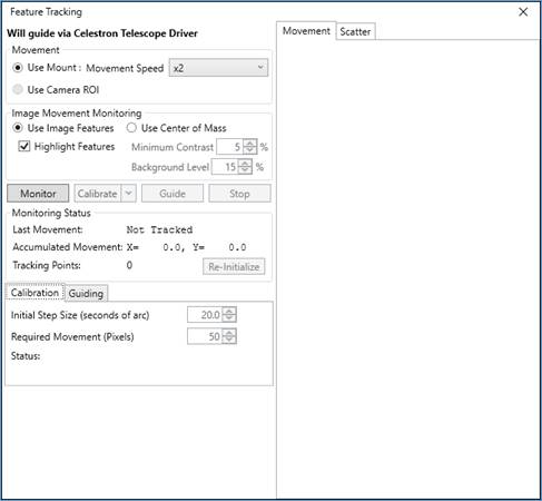
The top left of the Feature Tracking Window shows the hardware that will be used for guiding and allows the mount movement speed to be chosen if an ASCOM GOTO mount is being used. If appropriate guiding hardware is not selected, or not connected, a warning will be shown here and guiding functions will be unavailable. Note that the Use Camera ROI option will only be enabled when the camera Capture Area is set to a value smaller than the maximum, meaning that the ROI position can be moved.
There are two choices in the Tracking section – movement in the image can either be tracked by automatic detection of image features or by using the ‘centre of mass’ of the image brightness.
Choose Centre of Mass for tracking a planetary image where the only bright thing in view is the planet. Choose Feature Tracking for lunar or solar imaging. For other targets it may be best to try both and see which works best.
Starting Monitoring Image Drift
Press the Monitor button to begin monitoring the image for drift.
When using Center of Mass tracking, SharpCap will draw a cross on the image at the calculated position of the center of mass (brightness) in the image. Check that this cross really is in the center of the planet or other target and adjust the Background Level setting if necessary to exclude information from the darker parts of the image. You can also set the Minimum Contrast value – frames that have less than this amount of contrast between the darkest and brightest regions will not produce tracking info, helping exclude frames where the whole view of the camera is being obscured by cloud.
When using Image Features tracking, SharpCap will automatically find a range of identifiable feature points on the image and highlight them on-screen with small circles. As the image moves, these points will follow the feature on the image, allowing SharpCap to track how far the image has moved and in what direction.
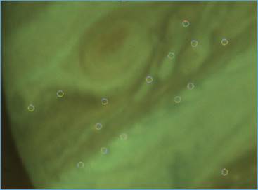
If the image is very low contrast or very out-of-focus then SharpCap may not be able to find sufficient image features to track accurately.
Tracking may be lost if
· The image moves very rapidly
· The image moves such a long way that most of the tracked features move out of view
· The image brightness is increased or decreased drastically
When image monitoring is active, the Monitoring Status area will be updated regularly.
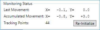
The Last Movement values show how far the image has moved between the most recent frame measured and the previous measured frame. The Accumulated Movement shows the total amount of image movement detected since monitoring was started. These measurements are in pixels.
The Tracking Points value shows how many features on the image SharpCap is currently tracking. If the number of tracked features falls then the Re-Initialize button can be used to find a new set of features to track while monitoring is still active.
You may wish to test if the tracking is working correctly by moving your mount slightly – this should be detected and lead to changes in the Accumulated Movement figures.
Calibration
SharpCap needs to work out which direction (and how far) the image moves when the mount is moved in the four different directions (RA +/-, Dec +/- or Alt +/-, Az +/-). This is affected by a wide range of factors such as camera orientation, telescope focal length, optical configuration of telescope, reducers or Barlow lenses being used, etc. In order to avoid having to enter all of the above information (which would be tedious and prone to error), SharpCap works out this information by moving the mount in each direction and measuring how the image moves – this process is known as Calibration.
One image monitoring is running successfully with a suitable number of tracking points, press the Calibration button to begin the calibration process.
Note that the ROI movement option does not perform any actual calibration – just press the Calibrate button and the user interface will immediately allow guiding to begin if you are in ROI mode.
During the calibration process, SharpCap will move the mount in each of the four directions, starting with small movements and gradually increasing the size until the image shift is detected. SharpCap will continue moving the mount until a total image shift of 50 pixels is measured (this value can be configured in the calibration settings). During the calibration process for each direction, a graph showing the measured image movement on the Y axis against the total mount movement on the X axis is drawn.
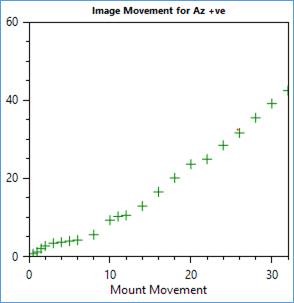
The graph should generally be a straight line, although as shown here it is common for the image not to move as much for the initial mount movements – this is due to backlash in the mount mechanism and should not normally cause a problem unless the amount of backlash is excessive.
During the four phases of the calibration process, a graph will build up in the Scatter tab showing how the image moved in response to each of the four mount movement directions. This graph should form the shape of an ‘X’ or cross. The two arms should be roughly straight, and close to being at right angles with each other.
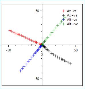
If the scatter plot does not resemble the one shown above then the calibration process may fail. Possible causes of calibration failure include:
· The image does not move in response to SharpCap moving the mount in one of the four directions
· The image moves at significantly different rates when the mount is moved in opposite directions
· When moving the mount in opposite directions the image does not move in opposite directions
· The direction the image moves when the mount is moved in the RA (or Az) axis is not roughly at right-angles to the direction the image moves when the mount is moved in Dec (or Alt)
The most likely cause of all of the above is excessive backlash in the mount movements. It may help to select a higher movement rate (if possible) to reduce the influence of backlash. Setting a higher Initial Step Size or Required Movement value may also help. The reason for any calibration failure will be shown in the Status area of the Calibration controls and more information may be available in the SharpCap guiding log, which can be found in the same folder as the normal SharpCap log files.
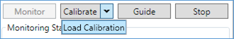
Once calibration has completed successfully, the Guide button will become enabled.
Note: After a successful calibration, SharpCap saves the calibration results so that they can be re-used later. If you return to Feature Tracking after re-starting SharpCap, you can choose to load the saved calibration by using the dropdown at the right-hand side of the Calibrate button.
The saved calibration will only be valid if you have not adjusted or rotated the camera and are still imaging in the same region of sky. Note that you can continue using the same calibration after performing a meridian flip – SharpCap detects this situation and adjusts the calibration data automatically to correct for the effective rotation of the camera after the flip.
Guiding in Action
After calibrating or loading a previously saved calibration, press the Guide button to begin guiding. SharpCap will then attempt to move your mount so as to keep the target roughly stationary in image. Note that SharpCap does not attempt to keep the target stationary to ‘pixel perfect’ levels – just to keep it from slowly drifting out of view.
The status of the guiding process can be monitored by checking the Accumulated Movement information, which should stay close to X=0 and Y=0 when guiding as active and also by viewing the Movement Graph, which shows both the history of image movement and corrections made

Red crosses on the Movement Graph represent measurements of the image position relative to the target position (the X and Y axes are measured in pixels). The most recent measurements are shown as larger red crosses while older measurements are smaller. Blue arrows represent guiding corrections made to bring the image back to the target position.
There are a number of adjustments that can be made to control the guiding procedure:
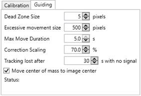
· Dead Zone Size – this is the size of the zone (in pixels) around the target position in which no guiding corrections at all will be made. The default is 5 pixels.
· Excessive movement size – detected movements of the image greater than this size will be treated as errors and ignored.
· Max Move Duration – the maximum length of a move command that will be issued (in seconds) as part of a guiding correction. The actual amount moved will depend on both this and the guiding rate chosen.
· Correction Scaling – the percentage of the calculated correction to apply when issuing a guiding command. Typically setting this between 50 and 70% ensures that there are no problems with over-correction or oscillation from one side of the target to the other, even if the calibration data is not 100% accurate.
· Tracking lost after – adjusting this option allows you to set a time limit for how long SharpCap will continue in the active guiding state when there is no movement signal being detected (perhaps because the target is temporarily obscured by clouds). When the movement signal has been lost for more than this length of time, tracking will stop and must be restarted manually. When the movement signal returns after a shorter loss than this, SharpCap will attempt to continue guiding without needing intervention.
· Move center of mass to image center – This option applies only in Center of Mass tracking mode – when enabled, SharpCap will move the center of mass of the image (most likely the planet) to the image center at the start of guiding. When disabled, SharpCap will leave guide by keeping the center of mass in its current position.