Automated Imaging in SharpCap
SharpCap now supports a number of options for automating imaging, including:
· Simple Sequence Captures – suitable for timelapses or repeated video captures
· The Deep Sky Sequence Planner for automating many aspects of deep sky imaging
· The Solar System Sequence Planner to automate capturing lunar/solar/planetary videos with different filters
· The Lunar and Solar Mosaic Planners, which automate capturing mosaic images of the moon and sun
· The Sequence Editor, which provides flexibility to do all of the above and much more by building and configuring lists of actions for SharpCap to carry out
Note that these features (aside from the Simple Sequence Captures) are SharpCap Pro features.
Deep Sky Sequence Planner
The Deep Sky Sequence Planner provides an easy-to-use way to plan and automatically execute a deep sky imaging session without needing to worry about the complexities of the SharpCap Sequence Editor. Most of the options you need for deep sky imaging are catered for by the planner, including:
· Camera setup
· Cool down and warm up of cooled cameras
· Target selection and framing
· Guiding and dithering
· Automatic focus
· Filter changing
Almost all of the actions that can be configured using the sequence planner can be tested individually using the Test buttons. Additionally you can run the entire plan sequence in either daytime or night-time Test Run mode. This ability to test gives you confidence that your sequence should execute as planned when you run it for real.
If you find that you cannot achieve the results you wish using the Deep Sky Sequence Planner, you may be able to achieve them using the SharpCap Sequence Editor, which has considerably more flexibility. You can even design the outline of a sequence in the Sequence Planner and then customize it further in the Sequence Editor by pressing the Advanced Edit button.
Note that you must have your camera selected in order to start the sequence planning process in SharpCap. Having the camera already selected allows SharpCap to tailor the options available to you to match the capabilities of your camera and any other hardware. It’s also good practice to have any ASCOM hardware (focuser, mount, filter wheel) connected while planning your imaging sequence. If you have ASCOM hardware selected but not connected then the Sequence Planner window will prompt you to connect it in order to enable hardware-related planning functionality such as autofocus and filter changes.
Note that the sequence planner will not be available for cameras that cannot run in still mode. Currently, this means that the following types of camera cannot be used with the deep sky sequence planner :
· Basler
· Celestron/Imaging Source
· Point Grey/FLIR
· The SharpCap Folder Monitor Camera
· Any webcam or USB frame grabber used via direct show drivers.
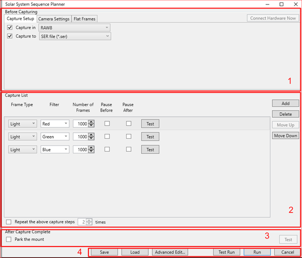
The Sequence Planner window can be divided
into four distinct areas as highlighted in the screenshot below :
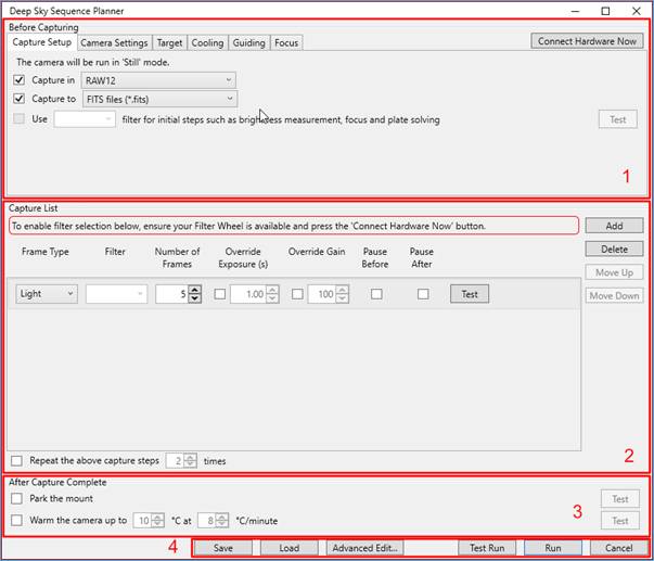
1. The Before Capturing section, in which you can specify camera parameters, information about the target that is to be imaged and make choices related to guiding, dithering, cooling etc.
2. The Capture List section. This section specifies all of the different captures that are to be carried out during the imaging session. These may include the capture of dark, flat and light frames and may also include filter changes, allowing LRGB or narrowband imaging to be sequenced.
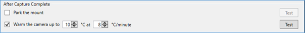
3. The After Capture Complete section. This specifies actions to be taken after the images have been captured – for instance warming up the camera or parking the mount
4. The Action Buttons. The buttons here can be used to save or load or run your sequence. You can also carry out a test run and to transfer the planned sequence into the full sequence editor for further customization.
To build your deep sky capture sequence, first choose the options that you would like to enable in the Before Capturing section, then build up the capture list with the appropriate entries for dark frames, flat frames, light frames etc. Finally, select the steps that you wish to run after the capturing is complete. More detail can be found in the sections below.
Note that SharpCap will automatically save changes that you make to the sequence planner and restore the most recent settings the next time you open the sequence planner window. You can also save plans for future reuse.
Before Capturing Options
Each of the tabs in the Before Capturing area allows you to set up a particular aspect of your imaging session.
Capture Setup
In this section you can choose the camera
colour space that will be used for all captures as well as the file
format that saved images will be written to. 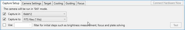
All captures during the sequence will be captured with the camera in still mode. Since the goal of the sequence is designed to be deep sky imaging, it is highly recommended that you use the highest bit depth available on your camera (i.e. RAW16, RAW14, RAW12 or MONO16, MONO14, MONO12).
The output format to save captured images to will depend upon your choice of software for processing those captured images, but in most cases choosing the FITS format would be best.
If a filter wheel is connected and you intend to capture with different filters, you can also specify here which filter should be used for initial steps such as focus, plate solving, etc.
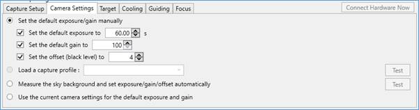
Camera Settings
In this section you can set up the most important camera settings such as exposure, gain and offset. Note that the default gain and default exposure set here will be used throughout the capture sequence except when they are overridden for a particular initialisation stage or capture step. The offset/brightness/black level chosen here is used throughout and cannot be overridden.
There are three ways that you can set up these parameters:
· Set each of the parameters manually
· Loading a previously saved capture profile that contains the desired camera settings (note that this approach can be used to set other camera settings beyond the exposure/gain/offset.
· Measuring the sky background and computing the most appropriate values based on upon the SharpCap Smart Histogram functionality. This is equivalent to using the Smart Histogram Brain functionality to measure the sky background and the settings that it recommends. This option will only be available if Sensor Analysis data is available for your camera.
· Make no changes – leave the current camera settings alone and use them for capturing.
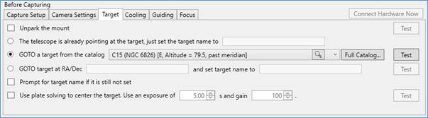
Target
In this section, you can set information about the target that you will be imaging. The range of options available here will depend on whether you have a GOTO mount configured and connected in SharpCap.
Without a GOTO mount, the only options available to you relate to setting the name of the target that will be used as part of the capture filenames created whilst the sequence is running.
If you have a GOTO mount configured in SharpCap but it is not connected, you will be prompted to press the Connect Hardware Now button to connect to the mount and enable the additional options.
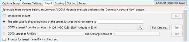
With a GOTO mount available, the following additional options are available to you
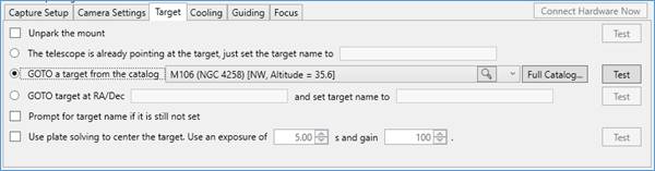
· Unpark the mount as the first step if necessary.
· Pick a target from SharpCap’s built in database of deep sky objects (currently this includes the Messier and Caldwell catalogues) and go to that target.
o Note that SharpCap shows not just the name of the target but also the current altitude and orientation of the target to enable easy selection of targets that are currently well clear of the horizon.
· Pick a target from SharpCap’s full catalog (including NGC, IC, Brightstar and any installed custom catalogs) by using the Full Catalog… button.
· Enter the coordinates and name of a target that you wish to image.
o The coordinates should be in RA/Dec notation and a wide variety of forms are accepted, for instance any of the following forms will be accepted as the co-ordinates of the Orion Nebula
|
05 35 17.3 -05 23 28 |
05 32 49.8 -05 25 21 |
|
RA 5h 35m 17s | Dec -5° 23′ 28″ |
5h 35m 17s -5° 23′ 28″ |
|
5h35m17.39s/Dec-5°23'28.24" |
RA= 5h 35.4m, Dec= -05° 27´ |
|
RA: 05h 35m 24.0s Dec: -05°27'00" |
5h RA, -5° DEC |
|
RA 05h 35.4m |Dec. -05° 27″ |
RA 05h 35.4m, dec. –05º 27’ |
|
{RA=05:35:16,Dec=-05:23:28} |
5.58805 -5.391 |
|
(05:35:20.556, -05:18:32.593) |
(83.84, -5.309) |
In all cases, RA co-ordinates are assumed to be in hours (not degrees) if the value is less than 24.
· Cause the sequence to prompt for the target name when executed if the name has not been set in some other way.
Finally, if you have a plate solving application configured as well as having a GOTO mount connected, you have the option of using the plate solving functionality to ensure that the target is centred in the field of view before starting to image. This is equivalent to using the Plate Solve and Resync tool.
Cooling
If your camera has a temperature controlled cooling system, you can choose to have the camera cool to a particular target temperature before the image capturing commences.

Guiding
If you wish to use guiding or dithering during your captures, you can configure it here. Before using this section, you should configure your guiding/dithering settings in the Guiding Settings.
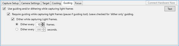
Note that if the ‘require guiding’ option is set then SharpCap will not only pause capture if guiding is lost, it will also actively try to restart guiding repeatedly to allow imaging to continue.
When a time interval is set for dithering, operations will occur at the end of the next frame to finish after the time interval expires. So, for example if dithering is set to occur every 300s with an exposure of 40s, dithering will occur after every 8th frame (7 frames take 280s, which will finish before the 300s dithering interval completes, so an 8th frame will start, which will finish after 320s).
Focus
If you have an ASCOM focuser connected then you have the option to configure SharpCap to perform an autofocus before imaging commences.
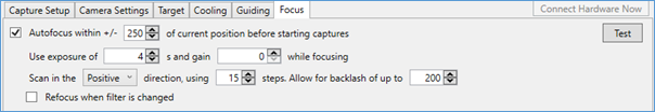
The autofocus procedure will use the Multi-Star FWHM Focus Measurement tool for best focus scanning, so you should make sure that you have tried that tool manually and configured any necessary settings before trying to use the autofocus option. The autofocus procedure is designed to bring the camera to best focus from a position that is already close to focus – it will not find focus if the camera starts a long way out of focus.
The following parameters can be set to configure the autofocus procedure:
· Focuser position range to scan – this is specified as an offset in each direction (+/-) from the current focuser position and should be large enough to ensure that the point of best focus is within the range.
· Exposure and gain to be used when capturing frames for focus. In general you will want to set a higher gain and shorter exposure to stop the focusing procedure from being exceptionally slow.
· The direction to scan in – this will also be the direction used for the focuser motion to the final best focus position.
· The number of measurement points to test the focus at between the minimum and maximum focuser position being scanned.
· A backlash allowance – this should be set to a value larger than the backlash amount of your focuser to ensure that backlash does not ruin the autofocus procedure. If you have configured backlash compensation then you can set this to a small value.
For instance, if your current focuser position is 13200 and you use the parameters shown above, SharpCap will scan between positions 12950 and 13450, measuring at 15 different positions (about 33 focuser steps between positions).
SharpCap will begin by moving to position 13450, then to 12750, then to 12950 before starting the scan – these moves clear any backlash on the focuser movement.
Finally, you can select the option to have the autofocus procedure repeated after any filter change. This may be considered as an alternative to defining focus offsets for the filters in your filter wheel.
The Capture List
A typical capture list is shown below – it specifies the type and ordering of image captures that SharpCap is to perform as part of the sequence. You can use the buttons on the right to Add, Delete and re-order the steps in the capture list to adjust it to match your imaging requirements.
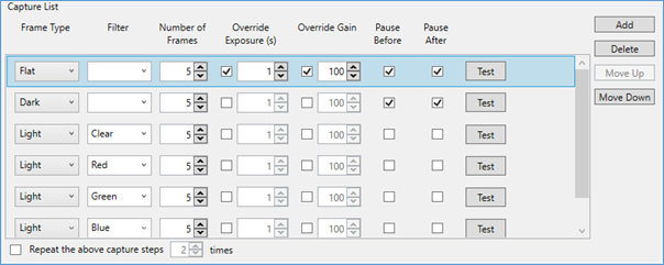
Each step in the capture list has the following properties which may be adjusted
· Frame Type – the frame type may be set to Light, Dark, Flat, Dark Flat, Bias or Other. The frame type is used to create the file names/directory names when saving the captured images – nothing else is changed when the frame type is altered.
· Filter – if you have a connected electronic filter wheel, you will be able to choose one of the filters in the wheel for each step. SharpCap will move the wheel to that position before capturing the frames for that step. Note that a blank entry in the filter column means that the filter wheel will not be moved before that step.
· Number of Frames – how many frames should be captured for that particular step
· Override Exposure – if the checkbox is ticked then the default exposure (set in the Camera Settings tab) will be changed to the specified value for this capture step. Following steps will not be affected by this change (they will use the default exposure unless they also set an exposure override).
· Override Gain – as for override exposure, ticking the checkbox and setting a value will set a different gain to be used for this capture step. Certain frame types (Flat, Dark Flat, Bias) will typically use override exposure and override gain as they are not captured with the same exposure/gain values as light and dark frames.
· Pause Before, Pause After – ticking one or both of these options will cause the sequence to pause before and/or after capturing the images in the step. During the pause, SharpCap will show a prompt – you will need to click ‘OK’ to continue the sequence. You can use the pause to set up flat frame illumination, cover the aperture for dark frames, etc. You can also adjust camera settings during the pause, which may be helpful to properly expose flat frames.
· Test – pressing the Test button will test the step – a test carries out all the actions associated with the step, but will only capture 1 frame, even if a larger Number of Frames is specified.
If you wish, you can configure the sequence to repeat all the capture steps in the sequence a number of times – this can be a useful option if you are unsure how much clear sky time you will have – instead of capturing 60 minutes with each filter, set up the capture steps for 15 minutes with each filter and repeat four times. If the clouds roll in after two hours, you still have data from each filter to work with.
After Capture Complete Options
These options are steps that can be taken after the capture steps have completed. You can choose to park the mount to the home position and (if you have a cooled camera) to warm it up at a gradual rate.
Testing and Running your Sequence
Testing individual steps
Automating your imaging using sequencing tools is a great way to improve your imaging productivity (or at the very least your comfort levels while the computer gets on with the imaging), but there is also a very real risk of wasting clear sky time if your imaging sequence doesn’t work properly and stops early because of an error.
Testing all parts of the sequence before running it for real is the best way of minimizing the chance of problems. The SharpCap sequence planner is designed to make testing of your sequence easy.
You can test individual setup or capture steps by using the Test buttons that you will find adjacent to many parts of the sequence planner options. Pressing one of these Test buttons will put together a shortened sequence that has the minimum amount of content needed to check the operation of the option you have chosen to test. Depending on the nature of the option being tested, it may be sufficient to test during daytime (for instance testing unparking of the mount or setting camera options), or it may require a clear view of the night sky (testing autofocus).
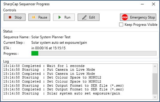
When you use the Test button for any of the individual steps, you will see the Sequencer progress window appear. SharpCap runs the test by creating a shortened sequence that contains only the steps that need testing (and any setup steps that are required in order to test them).
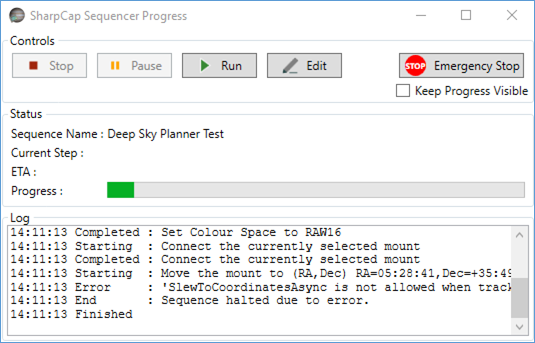
The test may take anything from a few seconds to a few minutes to complete. It’s a good idea to watch the progress of the test in the Log area of the progress window. If you see an ‘Error’ entry in the log then the test has failed – look at the message text that follows the ‘Error’ for information about the cause of the failure. In the screenshot shown above for instance, moving the mount to the target coordinates was being tested and it failed because the ASCOM mount would not allow the slow operation because the mount was not already tracking.
If the log shown in the progress window completes with no errors then the test is most likely successful, but it is still worthwhile checking – for instance if you are testing the autofocus procedure, check that the focus that it finds is really the best possible focus for the camera.
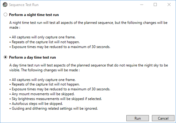
Testing the whole sequence
When you are happy that the individual steps are working correctly, it’s a good idea to test the whole sequence from beginning to end. You can do this by pressing the Test Run button.
![]()
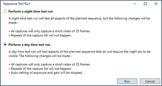
A test run is a quicker way to check all the steps in a sequence to make sure that they work without any problems. There are two types of test run that you can choose between:
· Night time test runs - these are the closest to the real execution of the sequence. The only changes are that exposure times are limited to 30 seconds; all captures are reduced to capturing only a single frame and any repeats of the capture steps are ignored. All set up and clean up steps will be executed – for example cooled down of the camera, focusing, moving the mount to point at the target, etc.
· Day time test runs - these are designed so that they can be performed without needing clear sky, and test as much of the sequence as possible subject to that limitation. All of the changes mentioned above for a Night time test run are applied along with the following extra changes to the full sequence:
o Mount movements and autofocus steps are ignored
o Sky brightness measurements will be skipped
o Guiding and dithering settings will be ignored
As with the testing of the individual steps, watch the output shown in the Log section of the Sequencer Progress Window during a test run to see if any problems occur. Also check the saved capture files afterwards (particularly for a night time test run) to make sure that they are in the correct format and contain image data of the quality that you would expect.
Running the Sequence
Running the sequence is very simple – simply press the Run button. This will start SharpCap’s sequencing engine running the steps that you have chosen and show the Sequencer Progress Window to allow you to follow the progress of the imaging sequence as it executes.
![]()
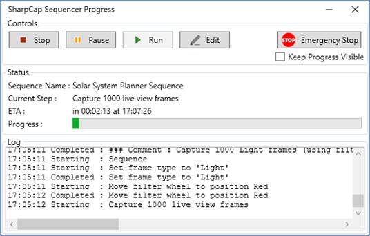
The Sequencer Progress Window
The Sequencer Progress Window is shown whenever a sequence is running (unless the main sequence editor is already visible). This window gives you the ability to monitor and control the sequence that is in progress, pause or cancel it if necessary and to perform an Emergency Stop if the situation requires it.
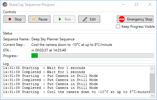
The Sequence Progress Window controls include the following :
· Stop - this will stop any sequence that is currently running. Note that the sequence may not stop immediately (depending on the action that is currently being carried out), but it should usually stop within a few seconds of the button impressed.
· Pause/Resume - this allows you to temporarily pause the sequence and to resume execution again after pausing. Pausing a sequence may take longer to take effect than stopping it. For instance if the sequence is currently capturing 60s exposure, stopping the sequence will cancel that exposure and stop fairly quickly. Pausing the sequence will wait until that exposure is completed before pausing.
· Run – this allows you to rerun a sequence from the start after it has finished or been stopped due to an error or manually.
· Edit - this will show the SharpCap Sequence Editor window, allowing you to make changes to the sequence that has been running.
· Emergency Stop – use this button if there is the risk of damage to equipment due to the commands being carried out by a running sequence. Pressing this button will not only stop the sequence as if the Stop button had been pressed, but will also send stop movement commands to any connected ASCOM mount or focuser.
· Keep Progress Visible - if this box is checked then the Sequencer Progress Window will remain visible above other applications even if SharpCap is minimised or another application is brought to the foreground.
The Status section of the progress window shows the following information:
· The name of the current sequence - this may be a file name if a sequence has been loaded from file or another descriptive name.
· The Current Step - this is the currently executing step in the sequence.
· The ETA - this section shows how long before the sequence is expected to complete and also the time at which completion is expected to occur. Note that this is just an estimate as some steps (for instance the measurement of sky brightness) may take a variable amount of time to complete. For some advanced sequences it may not be possible for SharpCap to calculate how long the sequence will take to run.
· Progress Bar - this is just a visible representation of how far much of the sequence has already been executed and how much is still to complete it.
The Log section of the progress window shows useful information for keeping track of the progress of the sequence. The beginning and end of every sequencer step are entered in the log, along with other information about the progress of certain steps and error information if an error occurs.
Note the information shown in the Sequencer Progress Log is also included in the main SharpCap log. A full list of the steps to be executed in any sequence that is run is also stored in the main SharpCap log to help with tracking down any problems that may arise.
Saving, Loading and Advanced Editing
Deep Sky Sequence Plans can be saved and reloaded later using the Save and Load buttons. Sequence plans are saved using the .ssp (SharpCap Sequence Plan) extension.
![]()
Note that while it is possible to load a plan that was previously saved for a different camera, care should be taken if the cameras have different capabilities as some of the settings in the saved plan may be ignored if they cannot be applied to the new camera.
Finally, it is possible to transfer the plan to the full SharpCap Sequence Editor for further refinement by pressing the Advanced Edit button. This will close the Sequence Planner window and open the Sequence Editor window with a representation of the plan loaded as the current sequence. The settings that you set up in the Sequence Planner window will be auto saved and restored the next time returned to the Sequence Planner.
Solar System Sequence Planner
The Solar System Sequence Planner provides an easy-to-use way to plan and automatically execute a solar system (video based) imaging session without needing to worry about the complexities of the SharpCap Sequence Editor. It is particularly aimed at capturing images using a monochrome camera and multiple filters, since this type of capture often has to be performed quickly. You can configure the basic settings needed for this type of imaging including:
· Capture format and camera exposure/gain settings
· Which filters to capture with and how many frames
· Per-filter flat frames to use if required
· Auto-exposure to set the correct exposure/gain for each filter
Almost all of the actions that can be configured using the sequence planner can be tested individually using the Test buttons. Additionally you can run the entire plan sequence in either daytime or night-time Test Run mode. This ability to test gives you confidence that your sequence should execute as planned when you run it for real.
If you find that you cannot achieve the results you wish using the Solar System Sequence Planner, you may be able to achieve them using the SharpCap Sequence Editor, which has considerably more flexibility. You can even design the outline of a sequence in the Sequence Planner and then customize it further in the Sequence Editor by pressing the Advanced Edit button.
Note that you must have your camera selected in order to start the sequence planning process in SharpCap. Having the camera already selected allows SharpCap to tailor the options available to you to match the capabilities of your camera and any other hardware. It’s also good practice to have any ASCOM hardware (focuser, mount, filter wheel) connected while planning your imaging sequence. If you have ASCOM hardware selected but not connected then the Sequence Planner window will prompt you to connect it in order to enable hardware-related planning functionality such as autofocus and filter changes.
The Sequence Planner window can be divided into four distinct areas as highlighted in the screenshot below:
1. The Before Capturing section, in which you can specify camera parameters, options on autoexposure, flat frames, etc.
2. The Capture List section. This section specifies all of the different captures that are to be carried out during the imaging session. Although you can specify different frame types, in practice only light frames make sense for Solar System captures. You may also include filter changes, allowing LRGB or narrowband imaging to be sequenced.
3. The After Capture Complete section. This specifies actions to be taken after the images have been captured – for instance parking the mount
4. The Action Buttons. The buttons here can be used to save or load or run your sequence. You can also carry out a test run and to transfer the planned sequence into the full sequence editor for further customization.
To build your solar system capture sequence, first choose the options that you would like to enable in the Before Capturing section, then build up the capture list with the appropriate entries for filters to be used, etc. More detail can be found in the sections below.
Note that SharpCap will automatically save changes that you make to the sequence planner and restore the most recent settings the next time you open the sequence planner window. You can also save plans for future reuse.
Before Capturing Options
Each of the tabs in the Before Capturing area allows you to set up a particular aspect of your imaging session.
Capture Setup
In this section you can choose the camera
colour space that will be used for all captures as well as the file
format that saved images will be written to. 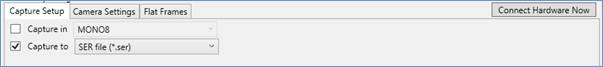
All captures during the sequence will be captured with the camera in video mode. In general, for solar system imaging a bit depth of 8 bits is sufficient, so the RAW8 or MONO8 colour space should be used. You may wish to use higher bit depths for solar imaging with narrowband filters if you are trying to capture detail of both the solar disc and prominences at the same time.
In general, it is best to capture all videos to the SER format, which is well supported by common video astronomy processing applications.
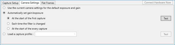
Camera Settings
In this section you can set up the how the
exposure and gain will be set during the captures. 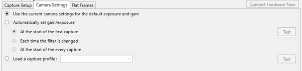
There are three ways that you can set up these parameters:
· Use the current camera settings unchanged throughout the procedure
· Allow SharpCap to automatically set the gain and exposure – this will be done to aim for a frame rate of at least 30fps. The automatic setting can either happen once for the whole sequence, every time a filter change occurs or at the start of every capture
· Loading a previously saved capture profile that contains the desired camera settings (note that this approach can be used to set other camera settings beyond the exposure/gain/offset.
Flat Frames
In this section you can configure the use of flat frames throughout the sequence. Flat frames are useful for this type of imaging as they correct for the shadows of any dust on the sensor. SharpCap is able to apply flat frame correction in real time to high speed video capture.
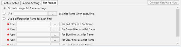
The options available are:
· To use whatever flat frame settings are already set up and not to change the flat frame settings during the sequence
· To specify a single flat frame to use throughout the sequence
· To specify flat frames per-filter – SharpCap will automatically change flat frames as the filters are changed during the sequence.
Note that any flat frames to be used in this section must have been prepared and saved beforehand – see Creating Flat Frames for more details on how to do this in SharpCap.
The Capture List
A typical capture list is shown below – it specifies the type and ordering of image captures that SharpCap is to perform as part of the sequence. You can use the buttons on the right to Add, Delete and re-order the steps in the capture list to adjust it to match your imaging requirements.
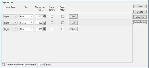
Each step in the capture list has the following properties which may be adjusted
· Frame Type – the frame type may be set to Light, Dark, Flat, Dark Flat, Bias or Other. The frame type is used to create the file names/directory names when saving the captured images – nothing else is changed when the frame type is altered. For solar system capture, you will normally leave this set to Light.
· Filter – if you have a connected electronic filter wheel, you will be able to choose one of the filters in the wheel for each step. SharpCap will move the wheel to that position before capturing the frames for that step. Note that a blank entry in the filter column means that the filter wheel will not be moved before that step.
· Number of Frames – how many frames should be captured for that particular step
· Pause Before, Pause After – ticking one or both of these options will cause the sequence to pause before and/or after capturing the images in the step. During the pause, SharpCap will show a prompt – you will need to click ‘OK’ to continue the sequence. You can use the pause manually change filters if you do not have an automatic filter wheel. You can also adjust camera settings during the pause, which may be helpful to properly expose the target.
· Test – pressing the Test button will test the step – a test carries out all the actions associated with the step, but will only capture 1 frame, even if a larger Number of Frames is specified.
If you wish, you can configure the sequence to repeat all the capture steps in the sequence a number of times – by setting a large value here, you can effectively set up your system to continuously capture your target in various filters over a long period, allowing an animation to be made from the final processed images.
After Capture Complete Options
These options are steps that can be taken after the capture steps have completed. For solar system sequences, the only option is to park the mount at the end of the sequence.
![]()
Testing and Running your Sequence
Testing individual steps
Automating your imaging using sequencing tools is a great way to improve your imaging productivity (or at the very least your comfort levels while the computer gets on with the imaging), but there is also a very real risk of wasting clear sky time if your imaging sequence doesn’t work properly and stops early because of an error.
Testing all parts of the sequence before running it for real is the best way of minimizing the chance of problems. The SharpCap sequence planner is designed to make testing of your sequence easy.
You can test individual setup or capture steps by using the Test buttons that you will find adjacent to many parts of the sequence planner options. Pressing one of these Test buttons will put together a shortened sequence that has the minimum amount of content needed to check the operation of the option you have chosen to test. Depending on the nature of the option being tested, it may be sufficient to test during daytime (for instance testing unparking of the mount or setting camera options), or it may require a clear view of the target (testing autoexposure for instance).
When you use the Test button for any of the individual steps, you will see the Sequencer progress window appear. SharpCap runs the test by creating a shortened sequence that contains only the steps that need testing (and any setup steps that are required in order to test them).
The test may take anything from a few seconds to a few minutes to complete. It’s a good idea to watch the progress of the test in the Log area of the progress window. If you see an ‘Error’ entry in the log then the test has failed – look at the message text that follows the ‘Error’ for information about the cause of the failure.
If the log shown in the progress window completes with no errors then the test is most likely successful, but it is still worthwhile checking – for instance if you are testing the autoexposure procedure, check that the exposure and gain that have been selected really do expose the target correctly and give the desired frame rate.
Testing the whole sequence
When you are happy that the individual steps are working correctly, it’s a good idea to test the whole sequence from beginning to end. You can do this by pressing the Test Run button.
![]()
A test run is a quicker way to check all the steps in a sequence to make sure that they work without any problems. There are two types of test run that you can choose between:
· Night time test runs - these are the closest to the real execution of the sequence. The only changes are that all captures are reduced to capturing only a short video of 25 frames and any repeats of the capture steps are ignored. All set up and clean up steps will be executed – for example setting camera colour space, output format, autoexposure, etc.
· Day time test runs - these are designed so that they can be performed without needing clear sky, and test as much of the sequence as possible subject to that limitation. In addition to cutting videos short to 25 frames and skipping repeats, this option will also skip any automatic adjustment of gain and exposure settings.
As with the testing of the individual steps, watch the output shown in the Log section of the Sequencer Progress Window during a test run to see if any problems occur. Also check the saved capture files afterwards to make sure that they are in the correct format and contain image data of the quality that you would expect.
Running the Sequence
Running the sequence is very simple – simply press the Run button. This will start SharpCap’s sequencing engine running the steps that you have chosen and show the Sequencer Progress Window to allow you to follow the progress of the imaging sequence as it executes.
![]()
The Sequencer Progress Window
The Sequencer Progress Window is shown whenever a sequence is running (unless the main sequence editor is already visible). This window gives you the ability to monitor and control the sequence that is in progress, pause or cancel it if necessary and to perform an Emergency Stop if the situation requires it.
More details can be found in the corresponding section for the Deep Sky Sequence Planner.
Saving, Loading and Advanced Editing
Deep Sky Sequence Plans can be saved and reloaded later using the Save and Load buttons. Sequence plans are saved using the .ssv (SharpCap Sequence Video) extension.
![]()
Note that while it is possible to load a plan that was previously saved for a different camera, care should be taken if the cameras have different capabilities as some of the settings in the saved plan may be ignored if they cannot be applied to the new camera.
Finally, it is possible to transfer the plan to the full SharpCap Sequence Editor for further refinement by pressing the Advanced Edit button. This will close the Sequence Planner window and open the Sequence Editor window with a representation of the plan loaded as the current sequence. The settings that you set up in the Sequence Planner window will be auto saved and restored the next time returned to the Sequence Planner.
Lunar and Solar Mosaic Planners
The SharpCap Lunar and Solar Mosaic planning tools provide an easy-to-use way to automate the capture of mosaic images of the moon and sun. After a brief alignment process, SharpCap will calculate the optimum arrangement of mosaic panels to cover the target and after fine-tuning of settings will proceed to perform the entire mosaic capture automatically.
The two mosaic planner tools will be available to use in the Sequencer menu providing the following conditions are satisfied:
· A camera is open and is in live view mode
· A GOTO mount has been configured for use in SharpCap and is connected
· The camera has square pixels and is not in an asymmetric binning mode
· Live stacking is not currently active
The GOTO mount is required to allow SharpCap to move the mount around during the mosaic capture procedure.
The following options can be configured to customize the mosaic capture process:
· Minimum overlap between panels
· Minimum safety margin around the edge of the target to be included in captures
· Whether to capture the whole disk or the illuminated portion (Lunar only)
· How many frames to capture for each panel
· Save format for videos and colour space to use for capture
· Whether to use autoexposure to set camera exposure and gain
· Configurable backlash take-up in RA and dec for each movement
· Optionally repeat the mosaic for multiple filters
Since the two mosaic planning tools are very similar in basic operation with just a few differences, both will be documented together rather than having separate documentation for each tool.
Before Starting a Mosaic
The mosaic tool in SharpCap does not check or adjust the focus of the image, so check that you have good focus before beginning the mosaic process. If you intend to use the option to use multiple filters then ensure that you have set up focus offset values in the ASCOM driver for your filter wheel for each of your filters and tested that they work correctly before attempting a mosaic.
Mosaic Alignment
The first stage of the mosaic capture procedure is to perform alignment. Alignment lets SharpCap work out four pieces of information that it needs in order to plan and run the mosaic:
· The size of the field of view of the camera (to work out how big each panel of the mosaic will be, and how many are needed)
· The orientation of the camera field of view relative to the movement directions of the RA and Dec axis (to work out the orientation of the target in the telescope’s view)
· The offset between the mount co-ordinates and the true pointing direction of the telescope in the region of the target (to allow SharpCap to correct for any error when sending GOTO instructions to the telescope)
· Whether the image is mirrored compared to the real view of the sky – this will be the case for telescopes that use an odd number of mirrors between sky and camera – for instance SCT or refractor with a diagonal.
Once SharpCap has worked out this information from the alignment procedure then the rest of the mosaic capture process can begin.
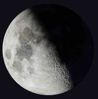
For a Lunar mosaic, SharpCap will show a
choice of alignment methods along with an image showing the current
phase of the moon. 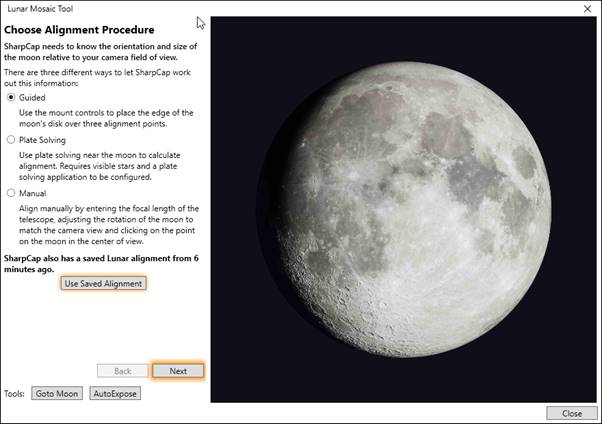
The possible alignment methods are:
· Guided – this method involves moving the mount to put one edge of the lunar disc onto three points that SharpCap will highlight onscreen. This is the recommended alignment method.
· Plate Solving – if you have already plate solved nearby then SharpCap can use that plate solving information for alignment purposes. If you have not plate solved yet, SharpCap can try to automate the process.
· Manual – Orient the on-screen moon image to match the view through the telescope, enter the focal length of your telescope and click on the on-screen moon to indicate where the camera is currently centered. This can be tricky to get right, particularly if you only see a small area of the moon through the telescope.
Additionally, if you have recently used the mosaic tool, SharpCap will show the option to re-use a previous set of alignment data.
For a Solar mosaic, the Plate Solving and Manual methods are not possible, so SharpCap will skip the choice of alignment methods and proceed directly to the beginning of the Guided alignment.
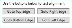
Note the two tools buttons at the bottom of the left hand side of the Mosaic Tool window.
![]()
These provide a quick way to move the GOTO telescope mount to the target (either Sun or Moon, as appropriate) and to auto expose the image on the camera. If you select the ‘Goto Sun’ button then you will be shown a warning about pointing the telescope at the sun – see Selecting the Sun as a GOTO Target.
Guided Mosaic Alignment
Guided Alignment is the recommended alignment technique, and the only one available for a solar mosaic. Guided alignment relies on using the GOTO mount movement buttons to place a selected point on the edge of the solar or lunar disc onto three alignment points that SharpCap will highlight onscreen.
Alignment point selection
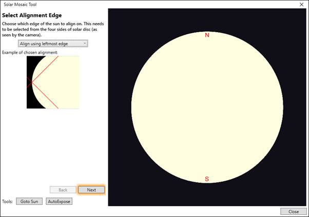
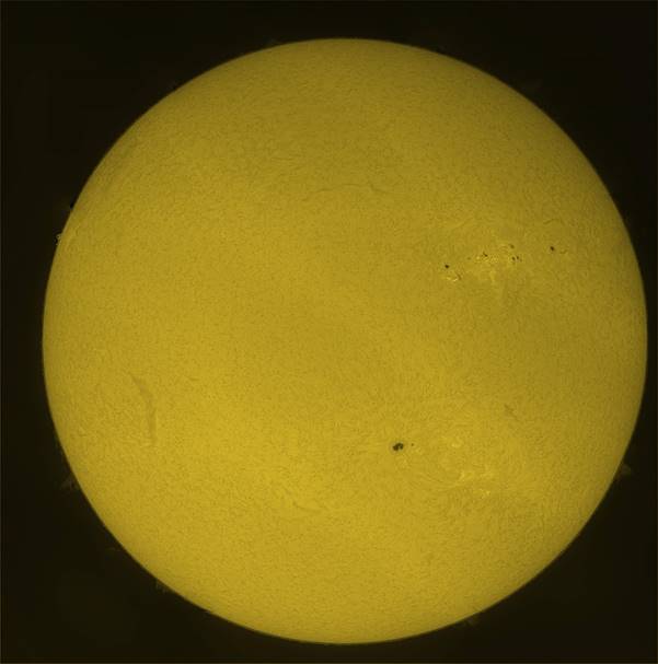
Only four points can be chosen for the selected point on the edge of the lunar/solar disc – the top-most, right-most, bottom-most and left-most points as seen in the camera view. For instance, the left-most point is highlighted in the solar image below.
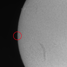
You need to select a suitable point from the four possibilities as the first stage of alignment.
When aligning on the sun, any of the four alignment points can be chosen. However, when aligning on the moon, typically only two of the points will show the edge of the lunar disc – the other two points are likely to be in the non-illuminated portion of the moon and are unsuitable. For instance, if the view of the moon through the telescope has the orientation shown below, you would need to choose either the left-most or bottom-most edge for alignment.
Once a suitable side of the target disc has been chosen for alignment, press the Next button to move on to performing the three alignment measurements.
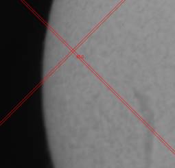
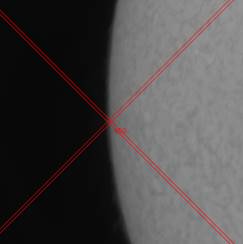
Adding Alignment Points
SharpCap will place a crosshair over the camera image – you need to use the mount movement controls (SharpCap shows a duplicate copy in the Mosaic Tool window) to move the mount so that the alignment point chosen is under the crosshair. For example, an incorrect alignment for left-most is shown on the left and a correct alignment is shown on the right
When performing the alignment, use the mount controls shown in the Mosaic Tool window.
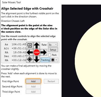
Select a low movement rate and use the left/right/up/down buttons to adjust. Note that the view onscreen will almost certainly move in a different direction to the button pressed due to rotation of the camera.
Once you have correctly aligned the selected alignment point with the crosshair, press the Add button to record the alignment point. SharpCap will then move the crosshair to a second position on the screen for the second alignment point – once again the selected point on the edge of the disc must be moved to the alignment point using the mount movement buttons before adding the second and then the third alignment points.
Things to note during the alignment procedure:
· Your mount may show backlash in movement in both the RA and Dec directions – in particular, if you move the mount in the easterly direction (opposite to the usual tracking motion to the west), the image may appear to drift for several seconds after the mount stops moving. To get best alignment, allow any drift to complete before deciding if you have aligned correctly.
· If you have considerable backlash in the Dec direction, consider always approaching each alignment point in a consistent direction (i.e. by using the North movement button for final adjustment on all points).
· You can use the mouse to move the crosshair slightly to perform the final adjustments for each alignment point, as long as most of the movement is done using the mount movement buttons.
· If you make a mistake, you can use the Restart button to clear the alignment points and start again with the first point. You can also use the Back button to go back to the previous stage and select a different alignment edge point.
· You may need to move the Mosaic Tool window around onscreen to properly see some of the alignment points.
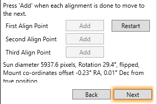
Once all three alignment points have been added, SharpCap will attempt to calculate the required alignment information. If this calculation is successful then SharpCap will display the summary of the alignment information and the Next button will become enabled
If there are significant inaccuracies in the alignment process then SharpCap may discover that the alignment calculations do not give consistent results. In that case an error may be shown ‘The Calculated mapping was not valid, please retry’. If you see this message, take extra care when retrying :
· Make sure that you are aligning to the correct chosen edge point for all three alignment points
· Make sure that you are allowing any drift to complete and correcting if necessary before adding an alignment point
· Take care to approach in declination from a consistent direction to avoid declination backlash being included in the calculations.
Plate Solving Alignment
Plate Solving Alignment is only available for lunar mosaics, and can only be used when the sky is dark enough to see sufficient stars for plate solving to work.
If you have already successfully plate solved near to the moon (within 10 degrees, ideally less) then SharpCap will use this information and immediately proceed to the next stages of the mosaic process.
If there is no plate solving information available, SharpCap will prompt you to either plate solve manually or use the Plate Solve Nearby button which attempts to automate the process.
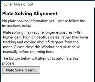
Note that you will probably be unable to plate solve directly adjacent to the moon due to the atmospheric glow that usually surrounds it on all but the clearest of nights – you will need to move the mount a few degrees away to find darker sky to plate solve.
Manual Alignment
Manual Alignment is only available for lunar mosaics, as it relies on identifying the orientation of the moon from the features visible on the lunar disc and the shape and orientation of the moon’s phase. You also need to identify the point on the moon that is currently in the center of view from its position in relation to the illuminated portion of the moon.
Important Note: The moon display shown in the Lunar Mosaic Tool is not a fully accurate image of the moon for the current date. It shows a typical lunar image with the correct phase, but does not include the effects of the moon’s wobble (libration) or the effects of the latitude and longitude of the observer on the view. This means that the positions of the craters, mares and other lunar features will not exactly match the positions seen on the real moon.
Setting Rotation
The first stage is to set the rotation of the moon to match the view through the telescope. This may be hard when the moon is close to full, or when the telescope only shows a very small area of the moon in the camera image.
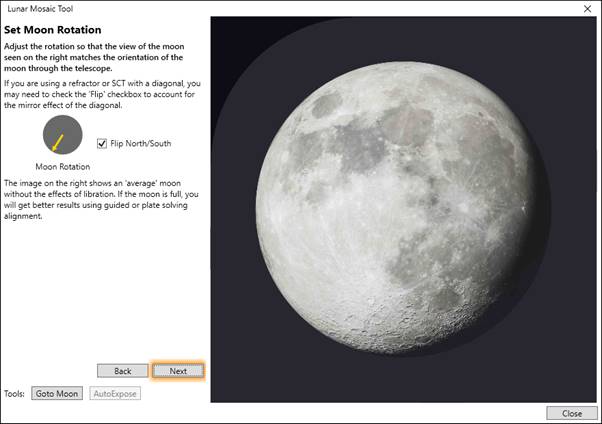
Move the yellow arrow in the moon rotation dial on the left to turn the moon image shown on the right to match the orientation seen through the telescope. If you are using a telescope with an odd number of mirrors in the light path between the moon and the camera then check the Flip North/South checkbox, which adds a mirror flip to the image shown on the right. This would typically be needed for SCT or refractor telescopes used with a diagonal mirror.
Once you have achieved the correct orientation, press Next to move on to the next stage
Setting the field of view
In this stage, you need to help SharpCap work out the area of the moon that is currently in view. This is done in two steps.
· Step 1: Set the focal length of the telescope that you are using (including the effects of any barlow lenses or reducers) and – if necessary – the pixel size of the camera.
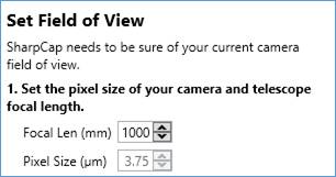
For most cameras, SharpCap will automatically detect the pixel size (and take into account any binning being used), so the pixel size will be pre-set and cannot be changed.
You will notice that a red box is drawn on the moon image on the right – this shows the size of the field of view of the camera for the currently selected focal length and pixel size. If you adjust the focal length then the size of this box will change.
Once the focal length and pixel size are set correctly, proceed to step 2.
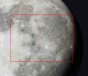
· Step 2: Click on the moon image to match the position red box to the current field of view of the telescope.
Since the moon image is not an exact representation of the current view of the moon, picking a lunar feature to do the alignment (such as a crater or sea) will give incorrect results.
You should base the alignment on a point picked in relation to the shape of the moon’s illuminated area, for instance by moving the telescope so that the center of view is at one end of the terminator (near the moon’s North or South pole) and then use that point for alignment. An example of this is shown below and should give accurate results.
Once an alignment point has been selected, the Next button will be enabled, allowing you to proceed to the next stage of the mosaic process.
Adjusting Mosaic Settings
Once SharpCap has calculated alignment data (by any of the available methods), the planning of the panels to capture in the mosaic can begin.
SharpCap will show the number of panels that are planned for the mosaic along with the arrangement of the panels, as seen below.
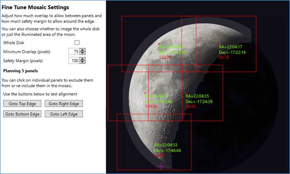
Each panel to be captured is represented by a red rectangle overlaying the image of the moon or sun on the right-hand side. The center of the panel is highlighted with a red dot. The image also shows the following features
· A halo around the moon or sun – this represents the safety margin. SharpCap will plan to include both the target and the safety margin area in the mosaic.
· A purple cross – this represents the expected current center of view of the camera, based on the alignment data.
· Green co-ordinates shown for each panel – these represent the mount co-ordinates that will be used to position the telescope for each panel
· A red brightness figure for each panel (only shown for lunar mosaics) – this represents SharpCap’s estimate of the maximum brightness of the panel. The brightest estimated panel will be used to auto set the camera exposure, if selected
· The red panel rectangles overlap each other – this represents the overlap between mosaic panels to ensure no gaps in the final image.
Adjustments can be made to the following settings:
· Whole Disk – this option is available for lunar mosaics only. When checked, SharpCap will include the whole lunar disc in the mosaic plan. When left unchecked, SharpCap will only capture the illuminated area of the moon, leaving out the dark areas.
· Minimum Overlap – this is the smallest overlap (measured in pixels) that SharpCap will allow between adjacent panels. SharpCap will use a larger overlap than this, providing using a larger overlap does not increase the number of panels needed.
· Safety Margin –this is the additional area (width measured in pixels) around the target that will be included in the mosaic.
The number of planned panels, and their arrangement, will update whenever any of the settings are adjusted.
Setting high values for Minimum Overlap and Safety Margin will help ensure that the mosaic is complete and has no gaps, at the expense of needing to capture more panels. Setting lower values will allow fewer panels, but runs the risk of missing parts of the target if the mount movement or the alignment measurements are inaccurate. A good starting point would be to set both to about 15% of the image height of your camera and then to adjust based on experience.
Manually excluding Panels
If you only wish to capture part of the target, you can manually exclude panels by clicking on each panel that you wish to exclude. An excluded panel will change to a grey rectangle. This may be useful to capture a region of the sun’s disc that has strong activity.
Excluded panels can be re-activated by clicking a second time.
Changing any of the settings (Whole Disk, Minimum Overlap, Safety Margin) will cause SharpCap to auto-recalculate the panel layout, which will reset all panels to being included.
Checking Alignment
You can also use the four Goto XXXX Edge buttons to test the accuracy of the alignment procedure to check that a good alignment was achieved and to help inform decisions on values for Minimum Overlap and Safety Margin.
If the alignment is correct, then when you use one of these buttons, the mount will be moved so that
· The pink cross indicating the mount position is in the appropriate place on the image of the target (top, right, bottom or left)
· The view through the camera will also have the top, right, bottom or left of the target (as appropriate) centered in view.
If there are significant errors in the camera view when using these buttons, you may wish to re-do alignment or increase the Safety Margin to capture a wider area around the target.
Adjusting Mosaic Panel Capture Settings
The final stage before starting the mosaic run is to specify what SharpCap needs to capture for each mosaic panel.
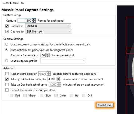
The options that can be adjusted relating to the captures are:
· Number of frames to capture for each panel – typical values might be 500 to 2000 frames, which can later be processed to produce a single image for each panel
· Colour Space to use – typically an 8-bit image will be sufficient (i.e., RAW8 or MONO8), but a higher bit depth may be useful if you are imaging the sun with a narrowband filter and wish to capture both prominences and surface features at the same time.
· Output file format – usually should be left set to SER, since this has the widest support and best compatibility.
Additionally, the camera settings can be setup as follows:
· Use current camera settings – the mosaic tool will make no changes to exposure, gain, etc.
·
Automatically set gain/exposure for the
brightest panel – if this option is
selected, SharpCap will initially move the telescope to the area
expected to be the brightest part of the mosaic. Once that area is
in view, SharpCap will auto set the camera exposure and gain to try
to achieve a well exposed image and also allow the requested frame
rate to be achieved.
All the panels will then be captured using those settings for gain
and exposure.
· Load a capture profile – load a previously saved capture profile to set the camera settings. Note that the profile may override settings for colour space and output file format set above.
Finally, a number of advanced settings can be adjusted:
· Add an extra delay before capturing each panel – this option may be useful if your telescope and mount take some time to settle after GOTO movements – by setting a delay you can avoid any initial vibration or drift being included in the captured videos
· Take up RA backlash on each movement – as mentioned previously, when an EQ mount is moved in the opposite direction to the normal tracking direction (i.e., moved in the +ve RA direction), on completion of movement, the image may appear to drift for some time while the RA backlash is taken up by the tracking motion.
Using this option can counteract this effect by ensuring that the final approach to each position is in the westward direction, meaning that the backlash is taken up automatically.
· Take up Dec backlash on each movement – if your mount has significant declination backlash then you may need to set this option to ensure that the approach to each set of co-ordinates is in the same direction in declination (northwards if set +ve, southwards if set -ve). You should also approach alignment points in the same direction when aligning.
· Repeat the mosaic for multiple filters – if a filter wheel is connected then SharpCap can automatically repeat the mosaic procedure for two or more selected filters. All the panels will be captured for the first filter before starting on capturing panels for the second filter and so on.
Note that changing filters often requires an adjustment to focus. To enable this to happen properly, you must have a connected ASCOM focuser and have set up focus offset values for each filter in your filter wheel configuration so that SharpCap can correctly adjust the focus at each filter change.
If using this option, it is a good idea to ensure that filenames include filter names by adjusting the Filename Settings to make identification of the captures for each filter easier.
One all of the capture settings have been adjusted to suit requirements, you can press the Run Mosaic button to start the mosaic process.
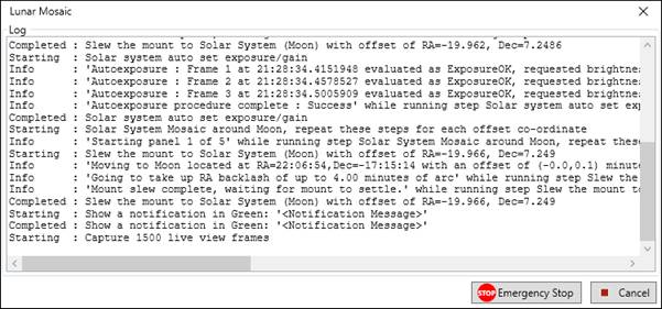
Running the Mosaic
Once the Run Mosaic button is pressed, SharpCap will begin to execute the mosaic plan. The Mosaic Tool window will remain open and will show the current status of the mosaic graphically, while an additional Mosaic progress window will appear showing detailed information about the steps that SharpCap is carrying out.
![]() The Mosaic Tool window shows
the progress as follows:
The Mosaic Tool window shows
the progress as follows:
· The current pointing position of the camera is shown with the purple cross, which updates as the mount is moved.
· Panels that are still the be captured are shown with their default red border.
· The mosaic panel that is currently being captured is shown with an amber border and an amber highlight.
· Panels that have already been captured are shown with a green border.
The progress window showing detailed steps being carried out also has Cancel and Emergency Stop buttons that allow you to stop the mosaic capture process before it completes if required for any reason. The Emergency Stop button will also stop any mount, rotator, focuser movement in progress.
When the mosaic capture is complete, you will find all the captured video files stored in a single folder for ease of processing – this folder will be located and named according to your normal SharpCap file naming settings.
On completion, the Mosaic Tool window will return to the Mosaic Panel Capture Settings page to allow you to quickly make any adjustments and run the mosaic again if you wish. You can also use the Back button to return to the adjustment of Safety Margin and Minimum Overlap if required.
Processing Mosaic Images
Each captured video can be stacked using normal video stacking tools (AutoStakkert!, Registax, etc.). However, Planetary System Stacker is a good choice for mosaic processing as it has a batch processing mode that will automatically work through multiple videos using the same settings for each.
Once the individual videos have been processed to stacked image files, software is required to ‘stitch’ the images into a single larger image. Software that can do this includes:
· Microsoft ICE (Image Composite Editor) – can be hard to find a download link
· Autostitch (http://matthewalunbrown.com/autostitch/autostitch.html)
· Adobe Photoshop (use Photomerge functionality)
· Affinity Photo 2 (use ‘New Panorama’)
Further processing of the stitched image may include stretching, sharpening and colorization for a solar mosaic.
The screenshot below shows the ‘New Panorama’ tool in Affinity Photo 2 being used to stitch a 3x3 solar mosaic.
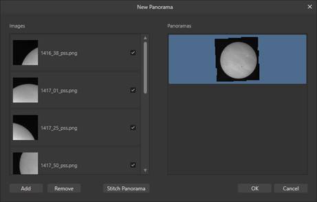
The resulting mosaic image is about 3600 pixels square, and a reduced resolution colorized version is shown below. The slight brightness variations across the image were the result of the temperature of the Quark filter having changed somewhat between capturing flat frames and capturing the mosaic.
The SharpCap Sequence Editor
The SharpCap Sequence Editor provides a much more flexible way of configuring SharpCap’s sequencing engine than the Deep Sky or Solar System sequence planners discussed above. Many automated imaging tasks that cannot be set up using the two sequences planners can be configured using the Sequence Editor. For example:
· Automating Live Stacking sessions.
· Automating imaging of multiple targets in succession.
· Automating capture of a mosaic of images.
These tasks are achieved by constructing an imaging sequence that consists of running a number of individually relatively simple steps in order. These steps can be thought of as building blocks from which the sequence as a whole is constructed. A full list of the available building block steps can be found below, but to give an idea of what is available, steps allow you to do things such as:
· Select a camera
· Change camera settings
· Capture frames as still images or a video
· Send commands to hardware – GOTO mounts, and electronic focusers and filter wheels
· Perform plate solving and autofocusing operations
· Wait for a fixed interval or until a time of day or an event (for example sunset)
· Repeat groups of other steps
· And many more – see Available Steps.
If you are familiar with computer programming, you may have spotted by now that the SharpCap Sequencer is essentially a very simple programming language. Some things that you might expect to find in programming languages (variables and conditional statements) have been deliberately left out of the SharpCap sequencer to prevent it from becoming too complicated.
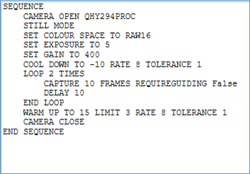
It’s important to be aware that the additional power and flexibility that is available through the Sequence Editor means that it’s possible to design sequences that are essentially nonsense. For example consider the following sequence :
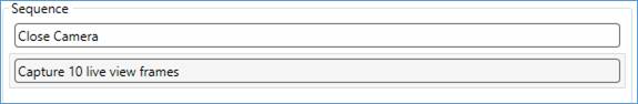
This sequence can never complete successfully – the first step closes any camera that is currently open and the second step tries to capture 10 frames. Attempting to capture the frames will always give an error because there will be no camera open when the capture frames step starts.
When designing your own sequences, think about the order that you would do things if you are using SharpCap manually and place the steps in the same order.
The Sequence Editor user interface
The Sequence Editor shows in a separate window to the main SharpCap window. You can display the Sequence Editor window at any time and it will automatically show the most recent sequence that you have worked on. You can keep the Sequence Editor window open and switch back to the main SharpCap window to perform non-sequence related tasks without needing to close down the editor window.
The initial view you will have of the Sequence Editor window (with no sequence loaded) will look like this:
The Sequence Editor Window is divided into nine major areas as highlighted below:
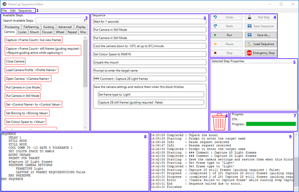
1. The Menu – this provides access to loading and saving sequences, standard editing operations such as cut/copy/paste and sequence run/stop/test commands.
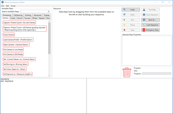
2. The Available Steps area - this area shows the list of sequencer steps that can be used to build up your own sequences. You can use the mouse to drag steps that you wish to use from this area into the main sequence list.
3. The Sequence list – this area shows the list of steps in your sequence. Each step shown here will be executed in order (from top to bottom) when you run the sequence.
4. The Action Buttons – these buttons provide quick access to common actions – Undo, Redo, Test, Run, Stop, etc
5. Selected Step Properties – when you click on a step in the Sequence List, any adjustable properties of the step will be shown and can be adjusted here.
6. Trash Can – drag steps here from the Sequence List to delete them.
7. Progress – the progress and ETA of a sequence are shown here when running a sequence from within the editor
8. Sequence Listing – this area shows the current state of the sequence in code form. Note that you cannot edit the sequence by making changes in this area, this is for information only
9. Sequence Log – sequence related log information is shown here when running a sequence from within the editor
The Menus
File Menu
The file menu allows actions relating to saving and loading sequence files. The choices available are:
· New - remove all steps from the current sequence so that you can begin designing a new sequence. Note that if you accidentally activate File->New without having saved your previous sequence, you can use the Undo button to go back to your previous sequence.
· Open – load a previously saved sequence from a *.scs file. The current sequence will be discarded.
· Save - save the current sequence back to file. This option is only available if the current sequence has already been saved or was loaded from file. Saving will overwrite the previous saved version of the sequence.
· Save As… - save the current sequence to a new *.scs file. You will be prompted to enter the file name for the new *.scs file.
Edit Menu
The edit menu provides operations to assist with editing sequences. Note that many of these operations have a keyboard shortcut which can also be used – the keyboard shortcuts are shown alongside each menu item and there is no need to open the menu to use the keyboard shortcut.
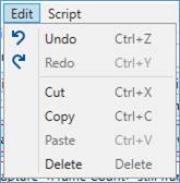
· Undo – undo the most recent change made to the sequence being edited. The addition, removal and reordering of steps as well as the changing of step properties can all be undone using the undo button.
· Redo - redo the most recent change that has been undone. Note that if you make other changes to the sequence after using the undo button then redo is no longer available.
· Cut/Copy/Paste - these are standard clipboard operations that allow you to remove, duplicate or rearrange steps in a sequence. These options are available providing that it least one step is selected within the sequence list.
· Delete – delete the currently selected steps from the sequence being edited.
Sequence Menu
The Sequence menu provides action related to running, stopping and testing sequences and their steps.
· Run - start running the current sequence from the beginning.
· Stop - stop any sequence that is currently running. Note that the sequence may not be able to stop immediately.
· Test Single Step - test the execution of a single step of the sequence. Using this option runs the currently selected step within the sequence being edited, allowing you to check that it works properly.
The Available Steps Area
This area displays the steps that are available to build up the sequence. Since there are a large number of available steps, they are grouped into categories such as Camera, Guiding, Focuser, etc.
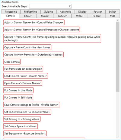
You can add steps from this area to your sequence in two ways:
1) Drag the step from the Available Steps area to the required position in your sequence.
2) Double click on the required step in the Available Steps area. This will insert it in the sequence just after the currently selected step.
Note that you can search the available steps by typing part of the name of a step that you wish to find into the Search Available Steps box. When you have entered text in the search box, any steps that do not contain your search text will be hidden, as will any step categories that no longer have any steps to show.
You can clear the search text in order to show all steps again – do this using the ‘X’ button to the right of the search text box or by deleting the text you have entered.
The Sequence List
The sequence list shows the steps that are currently a part of your sequence. When you run the sequence, these steps will be executed in order (top to bottom). Each step will begin after the step above has completed.
Some steps (for instance the Repeat 2 times step shown below) can have other steps placed inside them. The Repeat 2 times step is a parent step in this context and the steps it contains are sub-steps. In this particular case, the result will be that the sub-steps will be run twice during the execution of the sequence.
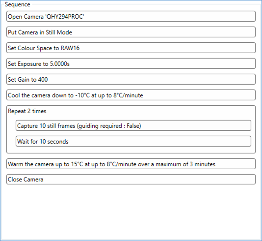
You can move steps around in the sequence list to re-order them by dragging them with the mouse. You can also drag steps into or out of parent steps, or between different parent steps.
If you click on a single step in the sequence list, any adjustable properties of that step will be shown in the Selected Step Properties Area. You can make adjustments to the values of the properties of the step – for instance changing how many frames will be captured, what the exposure should be set to or how many times to repeat a particular set of sub-steps.
You can delete steps that are no longer required by dragging them to the Trash Can or by selecting them and then choosing Delete from the Edit menu or by pressing the <Delete> key on your keyboard.
You can also use standard Cut/Copy/Paste functionality to work with the steps in the Sequence List. Once you have selected one or more steps, you can Cut or Copy them using the appropriate menu items or keyboard shortcuts. Choosing to Paste after steps have been Cut or Copied will add the steps after the currently selected step in the Sequence List.
The Action Buttons
The action buttons provide shortcuts to some of the items available in the File, Edit and Sequencemenus.
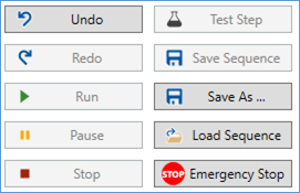
Additionally the Pause button which can be used to pause (and then resume) a running sequence.
The Emergency Stop button can be used if there is the risk of damage to equipment due to the commands being carried out by a running sequence. Pressing this button will not only stop the sequence as if the Stop button had been pressed, but will also send stop movement commands to any connected Ascom mount or focuser.
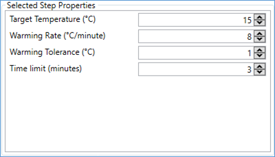
Selected Step Properties Area
Many steps have adjustable properties that configure exactly what the step does – for example the image below shows the properties of the Warm up Camera step – you choose the values for properties such as the Warming Rate and the Time Limit for this step.
When editing a sequence, it is best practice to have the camera that you intend to use to run the sequence open and to have any ASCOM hardware that you intend to use connected. This allows SharpCap to customize the ranges and options available in the various step properties for your configuration – for instance when configuring steps to set the exposure or gain of a camera, the correct minimum and maximum values will be enforced if the camera is connected.
Changes made to step properties can be undone using the Undo button or the Undo entry in the Edit menu.
Note that care should be taken when setting step properties, particularly if you adjust them when SharpCap is not connected to the device or camera that they will apply to. Incorrectly setting properties may cause the sequence to terminate with an error when run – for instance if you mis-spell the name of a filter, SharpCap will attempt to move the filter wheel to a filter that does not exist (perhaps ‘Grene’), leading to an error.
Trash Can
You can delete steps that are no longer required in the sequence by dragging them from the Sequence List to the Trash Can.

The Progress Area
The Progress area shows the current progress state of any running sequence.
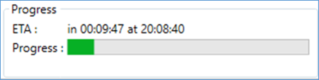
· The ETA - shows how long before the sequence is expected to complete and also the time at which completion is expected to occur. Note that this is just an estimate as some steps (for instance the measurement of sky brightness) may take a variable amount of time to complete. For some advanced sequences it may not be possible for SharpCap to calculate how long the sequence will take to run.
· Progress Bar - this is just a visible representation of how far much of the sequence has already been executed and how much is still to complete it.
Sequence Listing
The Sequence Listing area shows the current state of the sequence in code form – in fact the text shown is the text saved to the .SCS file when the sequence is saved. Some people who are familiar with computer programming may find this view of the sequence helpful.
Note that it is not possible to modify the sequence by editing the text shown in this listing area.
While it is technically possible to edit a sequence by saving it to .SCS file, editing the SCS file in a text editor and then re-loading it, this is not recommended. If any mistakes are made in editing the sequence file, SharpCap may give an error when attempting to re-load it.
Sequence Log
The Sequence Log shows information about what the sequencer is currently doing and what steps it has already completed when a sequence is running.
The start and completion of every step will be shown in the log, along with extra information for some steps (for instance a count of the number of still frames captured so far).
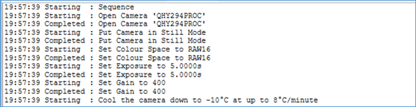
If an error occurs when running a sequence, there will be an ‘Error’ entry in the log which will explain the reason for the error – for instance :
21:07:02 Error : 'No camera selected.' while running step Capture 10 live view frames
Always check the Sequence Log for useful information if you have a problem when running a sequence. It may also be worthwhile checking the main SharpCap Log for additional information.
Working with the Sequence Editor
Following the guidelines laid out in the rest of this section will help ensure that you can design your imaging sequences quickly and accurately with as few problems as possible.
· Don’t try to use the sequence editor until you have become familiar with using SharpCap manually. Many of the steps available in the sequence a mirror manual actions that you can take in the SharpCap UI and being familiar with how they work and what order they should be used in will help when it comes to designing a sequence.
· Design your sequence with the camera that you intend to image with open in SharpCap. Also have any Ascom hardware connected to SharpCap. SharpCap can use information from the connected camera and ASCOM hardware to help ensure that step properties have the right minimum and maximum values and options available.
· Think about what you would do before you start running your sequence. You could design a sequence that you only run when the camera is already set up and the telescope is pointing at the target – that sequence might be fairly simple and start off by capturing frames. You could design and alternative version that will include all the setup steps – opening the camera, setting the camera settings, slewing the mount to point at the target, etc. it may be a good idea to start with the simpler version first and move on to the more complicated version later.
· Use the Test button frequently when you are designing your sequence to test individual steps and make sure that they do what you expect want to do and work correctly. If you want to test multiple steps then you can place them within a containing parent step temporarily – the Save the camera settings and restore them when this block finishes step can be useful for this purpose.
· Test all the different steps in your sequence individually before running the sequence as a whole, especially if you intend to run the sequence unattended.
· Don’t try to design a very complicated sequence straightaway – start with simple ones, make sure that they work as you expect and reliably before adding more complicated steps to your sequence gradually.
· Remember when designing a sequence that SharpCap will simply try to carry out the steps that you have selected even if they make no sense. If you are using SharpCap manually then you can’t try to capture images when there is no camera open because the capture buttons are all disabled. There is no such protection when you are designing an imaging sequence using the Sequence Editor – if you had a step that will try to start capturing when the camera is closed, SharpCap will attempt to carry out that step and then your sequence will end with an error.
Running your Sequence
You can run your sequence by using the Run button in the Action Buttons area or the Run menu item in the Sequence menu. Progress will be shown in the Progress Area and the Sequence Log.
If you close the Sequence Editor window while a sequence is running then the Sequencer Progress Window will be shown automatically to ensure that you still have the ability to see the progress of the sequence and to control its execution.
Note that the SharpCap menus and camera controls are disabled while a sequence is running – this is to prevent inadvertent actions or changes to the controls from interfering with the proper operation of the sequence. This also prevents you from closing SharpCap while a sequence is running. To close SharpCap or access the menus/toolbar, you must stop any running sequence.
The Show a prompt… step does allow you to optionally re-enable the adjustment of the camera controls while the prompt is waiting for the user to click OK. This is designed to allow manual adjustment of controls at appropriate points in the sequence (perhaps to set up the correct exposure for flat frame capture).
Available Steps
This section lists and describes all the available sequencer steps that can be used to build a sequence.
Camera
|
Step Name |
Description |
|
Open Camera '<Camera Name>' |
Open the named camera, closing any other camera that was already open. |
|
Close Camera |
Close any open camera. |
|
Put Camera in Live Mode |
Place the currently open camera into live mode (for video capture) |
|
Put Camera in Still Mode |
Place the currently open camera into still model (for deep sky imaging, for instance). Note that not all cameras support still mode. |
|
Start capturing frames |
Start capturing frames using the current camera settings. Note that frames will continue to be captured indefinitely (or until a Stop Capturing Frames) step is executed. |
|
Stop capturing frames |
Stop capturing on the selected camera. |
|
Start capturing now and then stop when <Astronomical Event> occurs |
Starts capturing immediately and then stops when the specified astronomical time of day occurs. The specified time of day can be any one of : Astronomical Midnight, Astronomical Dawn, Nautical Dawn, Civil Dawn, Sunrise, Solar Noon, Sunset, Civil Dusk, Nautical Dusk, Astronomical Darkness. Note that depending on your latitude and the time of year, some events may not occur. An error will occur if the selected event does not occur in the next 24 hours. |
|
Capture <Frame Count> live view frames |
Capture the specified number of frames in live view mode. The camera will be placed in live view mode if it is currently in still mode. |
|
Capture live view frames for <Duration> seconds |
Capture live view frames for the specified amount of time. The camera will be placed in live view mode if it is currently in still mode. |
|
Capture <Frame Count> still frames (guiding required : <Require guiding active while capturing>) |
Capture the specified number of frames in still mode. The camera will be placed in still mode if it is currently in live view mode. If the Require guiding active option is set then SharpCap will take the following additional steps: · An error will occur if a guiding application is not being monitored (see the Monitor Guiding Application step) · Capture will be paused if guiding is not active · SharpCap will attempt to restart guiding and will resume capturing if guiding resumes · SharpCap will discard any frame that is less than 95% complete when guiding is lost (an extra frame will be captured to compensate) |
|
Load Camera Profile '<Profile Name>' |
Load all of the capture settings stored in the named capture profile. |
|
Save Camera settings to Profile <Profile Name> |
Save all of the camera settings to a capture profile with the given name |
|
Set Output Format to <File Save Format> |
Set the output format for saved images/videos to the specified format. |
|
Set Resolution to <Value> |
Set the camera resolution to the specified value |
|
Set Colour Space to <Value> |
Set the camera colour space to the specified value |
|
Set Binning to <Binning Value> |
Set the binning of the camera to the specified value |
|
Set Exposure to <Exposure Length>s |
Set the camera exposure to the specified length. Note that exposures of less than 1s can be set – for instance 0.030s for 30ms. |
|
Set Gain to <Gain Value> |
Set the camera gain to the specified value. |
|
Set offset to <Offset/Brightness Value> |
Set the offset/black level/brightness of the camera to the specified value |
|
Set <Control Name> to <Control Value> |
Set another camera control to the specified value. Use this step to set controls that do not have a more specific step (such as gamma, white balance controls, etc). |
|
Adjust <Control Name> by <Control Value Change> |
Adjust the value of a camera control by the specified amount – this allows changes to be made relative to the current value of the control. The value change is added to the current value to give the new value, so a negative change will reduce the control value. |
|
Adjust <Control Name> by <Control Percentage Change> percent |
Adjust the value of a camera control by the specified percentage amount. A percentage change of zero will do nothing, a change of +5% will increase the value by 5% (i.e. multiply the current value by 1.05). Values less than zero will reduce the value of the control. |
|
Flat frame auto set exposure/gain |
Attempt to auto-set the exposure and gain of the camera to settings that are suitable for capturing flat frames. SharpCap will ideally try to get the histogram range 50% and 80%, but will allow a rough balance between pixels above 80% and below 20% as long as there are only a handful of pixels above 95% or below 10% brightness. |
|
Solar system auto set exposure/gain |
Attempt to auto-set the exposure and gain of the camera for solar system capture. SharpCap will initially set an exposure that should allow the TargetFPS rate to be achieved (i.e. 10ms if a TargetFPS of 100 is set). SharpCap will then increase the gain until the brightest parts of the image are somewhere between 70% and 90% of maximum brightness. If necessary SharpCap will lower the exposure further to achieve correct brightness. |
|
Set exposure/gain for plate solving and focus while running these steps |
Attempt to set a shorter exposure of 4s and a higher gain to compensate for the shortened exposure. The sub-steps within this step are then run with the camera using the shorter exposure and higher gain. When the sub-steps have been completed, the original exposure and gain settings are restored. This step is a useful way of temporarily changing to short exposure, high gain frames while focusing, plate solving, etc. Note that the compensation for reduced exposure by using increased gain is only accurate if SharpCap understands what effects changes to the gain value of the camera have on image brightness – see What does a gain value mean? for more information. |
|
Wait for next live view frame |
In live view mode, this step will wait until the camera next provides a new frame, and then wait a further 0.5 seconds. This step can be helpful to allow a new frame to arrive after moving the mount, focuser or rotator to ensure that the next frame to arrive from the camera will not be affected by the movement. In still mode, this step does nothing as all frames must be directly requested from the camera. |
|
Start capturing now and stop when <Astronomical Event> occurs |
This is a convenient shortcut that will start capturing, then wait until the selected astronomical event occurs, then stop capturing. Note that if the event has already happened on that day, it will stop capturing immediately – i.e. if the event chosen is ‘Dawn’, but this step is run after dawn has happened, it will stop capture straight away. |
Cooler
|
Cool the camera down to <Target Temperature>°C at up to <Cooling Rate>°C/minute |
Cool the camera down to the specified target temperature. The rate of cooling can be limited, as can the tolerance (how close to the target temperature the camera must get for the step to be considered finished). The camera will have its cooler turned on (if necessary) and the cooler will also be put into automatic (temperature controlled mode) if necessary. If the camera does not have a cooler, or the cooler is not temperature controlled then an error will occur. If the target temperature set is warmer than ambient temperature, or if it is colder than the coldest temperature that the camera cooler can achieve then this step may never finish as the camera temperature will never reach the target. |
|
Set the target temperature to <Target Temperature>°C |
Change the target temperature for the camera cooler to the specified temperature. |
|
Turn the camera cooler off |
Turns off the camera cooler by one of the following three means: · If the camera has a cooler on/off control, set it to off. · If the camera has a manual cooler power control, set the cooler power to 0% · If the camera has a temperature controlled cooler, set the target temperature to the maximum value. Note that using this step on a cooled camera may cause the sensor temperature to rise rapidly. |
|
Warm the camera up to <Target Temperature>°C at up to <Warming Rate> °C/minute |
Warm the camera up to the specified target temperature. This mirrors the cool down step in that warming rate and completion tolerance can be specified. Additionally, a time limit can be set for this step – the step will complete when the time limit expires even if the warming procedure is not complete. |
Mount
|
Select Mount '<Mount Name>' |
Make the named mount the selected mount – this is equivalent to changing the mount that SharpCap uses in the Hardware Settings. |
|
Connect the currently selected mount |
Attempt to connect to the currently selected mount if it is not already connected. This could cause an error if the mount is not connected to the computer or not configured correctly. |
|
Disconnect the currently selected mount |
Disconnect from the currently selected mount. Other mount related operations will not be possible after this point until a mount is connected again. |
|
Unpark the mount |
Unpark the mount if it is parked |
|
Park the mount |
Park the mount to the default park position |
|
Move the mount to (RA, Dec) <RA/Dec co-ordinates> |
Slew the mount to the specified co-ordinates. See co-ordinates in the sequencer for details on the formats that are accepted for RA/Dec co-ordinates. |
|
Move the mount to Alt=<Altitude>, Az=<Azimuth> |
Slew to the mount to the specified altitude/azimuth co-ordinates. Note that not all mounts support AltAz co-ordinates. |
|
Offset the mount position by RA=<Right Ascension Offset>, Dec=<Declination Offset> |
Offset the current mount position by the specified offsets in RA and Declination. This may be useful for moving a target slightly off centre in the field of view. |
|
Plate solve a single frame, sync the mount and re-GOTO the target co-ordinates |
Re-centre the target using plate solving. This is equivalent to using the Plate Solve and Resync tool and follows the same configuration options as that tool. |
|
Plate solve a single frame and sync the mount only |
Perform the plate solving and sync of the mount, but no action will be taken to adjust the mount position after the sync step. At this point, since a sync has just happened, nearby GOTO movements should be accurate. |
|
Set mount tracking rate to <Tracking Rate Name> |
Set the mount tracking rate. The available options are None (tracking stopped), Sidereal, Lunar, Solar, King. |
|
Goto the sky co-ordinates of <ImageFile> |
Plate solve the astronomical image found in the <image file> and then move the mount to the co-ordinates generated by the plate solving operation. This should return the mount to the position of a previous image, although a Plate solve a single frame, sync the mount and re-GOTO the target co-ordinates step should follow to refine the position |
|
Save the current mount co-ordinates
|
Store the current mount co-ordinates in the internal storage of the SharpCap sequencing engine. The saved co-ordinates remain available until overwritten by another step that saves co-ordinates or the sequence ends. This step may be used with the Move the mount to a set of co-ordinates that were previously saved step to allow the mount to move away from and return to a position without needing to specify the exact co-ordinates of the position to return to in the sequence. |
|
Move the mount to a set of co-ordinates that were previously saved |
The mount will be moved to the most recent set of saved co-ordinates. |
|
Plate solve and save co-ordinates |
Capture a frame from the camera and then plate solve it. Store the co-ordinates that are found by the plate solving in the internal storage of the SharpCap sequencing engine. This step could be used to store the current pointing position of the mount before attempting a meridian flip, then after the flip the Move the mount to a set of co-ordinates that were previously saved step could be used to return to the same co-ordinates |
|
Sync the mount to a set of co-ordinates that were previously saved |
Take the saved co-ordinates and issue a sync command to the mount using those co-ordinates. |
|
Slew the mount to Solar System <Target> with offset of RA=<RA Offset> Dec=<Dec Offset> |
Move the mount to a solar system target (sun, moon, 8 planets, Pluto) with an optional offset from the center of the target specified in arc minutes in RA and Declination. |
|
Meridian flip the mount (experimental) |
This step will attempt to perform the actual mechanical flip of the mount from being on the west side of the pier pointing east to being on the east side of the pier pointing west. Depending on the capabilities of the ASCOM mount in use, different techniques may need to be used to ensure that the movement happens. Once the mount has moved across the meridian, further steps can re-point the mount at the target, etc. to continue an imaging session. |
Focuser
|
Select Focuser '<Focuser Name>' |
Make the named focuser the selected focuser – this is equivalent to changing the focuser that SharpCap uses in the Hardware Settings. |
|
Connect the currently selected focuser |
Attempt to connect to the currently selected focuser if it is not already connected. This could cause an error if the focuser is not connected to the computer or not configured correctly. |
|
Disconnect the currently selected focuser |
Disconnect from the currently selected focuser. Other focuser related operations will not be possible after this point until a focuser is connected again. |
|
Move focuser to position <Focuser Position> |
Move the focuser directly to the position specified. For example move the focuser to position 11950. |
|
Move the focuser by <Focuser Offset> |
Move the focuser by an offset from its current position – a negative offset will move the focuser to smaller position values, a positive offset to larger position values. |
|
Autofocus between <Start Focuser Position> and <End Focuser Position> with <Scan Step Count> steps allowing for backlash up to <Backlash Allowance> |
Perform a multi-star FWHM based autofocus between the two focuser positions specified.
See the documentation on focusing in the sequence planner for more details. |
|
Autofocus from offset <Start Focuser Position (Offset)> to <End Focuser Position (Offset)> with <Scan Step Count> steps allowing for backlash up to <Backlash Allowance> |
Identical to the above autofocus step except that the start and end points are defined relative to the current focuser position rather than with absolute focuser position values. |
|
Refocus using the same settings as the most recently used autofocus run |
This will run a refocus using the focus tool and settings of the most recently used autofocus run, equivalent to using the Automatic Refocus option from the focus tools. |
Wheel
|
Select Filter Wheel '<Filter Wheel Name>' |
Make the named wheel the selected filter wheel – this is equivalent to changing the filter wheel that SharpCap uses in the Hardware Settings. |
|
Connect the currently selected filter wheel |
Attempt to connect to the currently selected filter wheel if it is not already connected. This could cause an error if the filter wheel is not connected to the computer or not configured correctly. |
|
Disconnect the currently selected filter wheel |
Disconnect from the currently selected filter wheel. Other filter wheel related operations will not be possible after this point until a filter wheel is connected again. |
|
Move filter wheel to position <Filter Name> |
Move the filter wheel to a new position (specifying the name of the filter to move to). |
|
Move filter wheel to position <Filter Wheel Position> |
Move the filter wheel to a new position (specifying the filter position number to move to – these numbers count upwards from 1 to the number of filters on the wheel). |
Rotator
|
Select Rotator '<Rotator Name>' |
Make the named rotator the selected rotator – this is equivalent to changing the rotator that SharpCap uses in the Hardware Settings. |
|
Connect the currently selected rotator |
Attempt to connect to the currently selected rotator if it is not already connected. This could cause an error if the rotator is not connected to the computer or not configured correctly. |
|
Disconnect the currently selected rotator |
Disconnect from the currently selected rotator. Other rotator related operations will not be possible after this point until a rotator is connected again. |
|
Move rotator to angle <Target Angle> |
Commands the rotator to rotate the camera to the given angle (absolute angle) |
|
Turn rotator by angle <Rotation Angle> |
Commands the rotator to rotate the camera by the given angle (relative angle) |
|
Plate solve and save image orientation |
Captures an image from the camera, plate solves it and saves the orientation of the image in the internal storage of the SharpCap sequencer engine. The rotation is then available until it is overwritten by using this step again or the sequence ends. |
|
Plate solve and return image to saved orientation |
Captures an image from the camera, plate solves it and then uses the rotator to adjust the rotation so that the camera orientation returns to a position that matches the saved orientation. |
Switch
|
Select Switch '<Switch Device Name>' |
Make the named switch device the selected filter switch device – this is equivalent to changing the switch device that SharpCap uses in the Hardware Settings. |
|
Connect the currently selected Switch device |
Attempt to connect to the currently selected switch device if it is not already connected. This could cause an error if the switch device is not connected to the computer or not configured correctly. |
|
Disconnect the currently selected Switch device |
Disconnect from the currently selected switch device. Other switch related operations will not be possible after this point until a filter wheel is connected again. |
|
Set switch <Switch Name> to <Switch Value> |
Set the ASCOM switch identified by <Switch Name> to the value specified. Each switch device defines its own switch names, but this might be used, for instance, to turn a dew heater on or enable 12V power to a camera cooler. |
Repeat
Each repeat type step can have one or many other steps placed within it as sub- steps. These sub- steps will be run one or more times depending on the type of repeat specified by the repeat step.
|
Repeat <Repeat Count> times |
Repeat the sub- steps a fixed number of times. |
|
Repeat until <Astronomical Event> occurs |
Continue repeating the sub steps until the time of day specified by <Astronomical Event> occurs. The specified time of day can be any one of : Astronomical Midnight, Astronomical Dawn, Nautical Dawn, Civil Dawn, Sunrise, Solar Noon, Sunset, Civil Dusk, Nautical Dusk, Astronomical Darkness. Note that depending on your latitude and the time of year, some events may not occur. An error will occur if the selected event does not occur in the next 24 hours. Note that no new runs through the sub steps will begin after the specified time, but any sub- steps in progress at the specified time will continue running until the end of the list of sub- steps is reached. |
|
Repeat for each filter in <Filter List> |
Repeat the sub-steps once for each of the filters specified in the filter list. |
|
Repeat for each Alt/Az co-ordinate in <Co-ordinate list file> |
Repeat the sub steps once for each set of altitude/azimuth coordinates listed in a text file. The text file should contain one coordinate pair per line. |
|
Repeat for each RA/Dec co-ordinate in <Co-ordinate list file> |
Repeat the sub steps once for each set of RA/declination coordinates listed in a text file. The text file should contain one coordinate pair per line. See coordinates in the sequencer for more details on the format required for these coordinate values. Note that it is also acceptable to place a target name at the start of each line – SharpCap will then use this name as the observing target for or file naming as well as using the coordinates values from that line. The target name should be separated from coordinates by a comma. For example: M42, 05 35 17.3 -05 23 28 |
|
Repeat until <Time of Day> |
Repeat the sub steps until the specified time of day is reached. Note that the time is only checked each time a new loop through the sub-steps is started, so the step may execute beyond the specified time of day, but will not start a new loop through the sub-steps beyond that time. If the specified time of day has already passed for today then the steps will be repeated until that time of day tomorrow. |
|
Repeat until <Astronomical Event> occurs |
Repeat the sub steps until the specified Astronomical Event occurs. Note that if the specified astronomical event does not occur in the next 24 hours (i.e. Astronomical Darkness in the summer in midlatitudes) then an error will occur. |
|
Solar System Mosaic around <Target>, repeat these steps for each offset co-ordinate |
Carries out the sub-steps for each offset position around the specified solar system target. Offsets must be specified in minutes as follows: 1.2345,6.7890;2.3456,7.8901 Note that the decimal separator must be a ‘,’ and the separator between co-ordinates must be a ‘;’. A co-ordinate pair contains the RA offset first and the declination offset second, separated by ‘,’. Note that the RA offset is specified in minutes as 1/60th of an hour of RA, whereas the declination offset is in minutes as 1/60th of a degree of declination. This step is designed for internal use by the Lunar/Solar mosaic tools, so should be used with caution. |
Misc.
|
Connect the all currently selected hardware |
Connect all the hardware that is currently selected – this is a shortcut for connecting the focuser, mount and filter wheel individually. Note that there won’t be an error if there are hardware categories that do not have a selected device. |
|
Disconnect all currently selected hardware |
Disconnect all currently selected hardware. Again a shortcut for individually disconnecting the mount, focuser and filter wheel. |
|
Play the <Sound to Play> sound. |
Play a Windows sound on the standard sound device of the computer. You have the choice between two different sounds – alert and error. The sounds that play for these two options can be configured in the ‘Change System Sounds’ section of the Windows Control Panel. |
|
Run '<Program to run>' with parameters '<Arguments>' and <Wait for command to exit?> |
Run another Windows or Command Line application, optionally waiting for the other program to finish before continuing. It is best to specify the program to run by its full path (or to select it using the Browse button). You can also specify command line parameters to be passed to the program being run. It is possible to run batch files or PowerShell scripts using this step to perform more complicated actions. |
|
Save the camera settings and restore them when this block finishes |
This step can have multiple sub steps added to it. The camera settings in effect at the beginning of the step are stored and then reapplied to the camera after the sub steps have completed. Using this step can be useful to allow alternative camera settings used for a particular task (for instance focusing) before returning the camera to the original settings. |
|
Show a countdown for <Delay> seconds with message <Message Text>. |
This step will show a message on screen for a fixed number of seconds (showing the number of seconds remaining as a countdown). |
|
Show a notification in <Notification Colour>: '<Notification Message>' |
This step will show a notification in the SharpCap notification bar, allowing you to choose the text to be shown and the colour of the notification bar. |
|
Show a prompt '<Message Text>' and wait for OK to be pressed. Camera controls enabled : <Enable Camera Controls> |
Show a prompt window containing a message and wait for the user to press the OK button before continuing. Optionally, you can allow the camera controls to be re-enabled during the period that the prompt is shown – this allows adjustments to be made, perhaps to get correct flat frame exposure levels. |
|
Wait for <Delay> seconds |
Pause the sequence for the number of seconds specified before continuing. |
|
Wait until <Time of Day> |
Wait until the specified time of day before continuing. Note that the time specified is a local time. If the time of day specified has already passed then SharpCap will wait until the same time tomorrow. |
|
Wait until later than <Time of Day> |
Wait until later than the specified time of day before continuing. Note that the time specified is a local time. If the time of day specified has already passed today then SharpCap will not wait at all. |
|
Wait until <Astronomical Event> happens (or has already happened) |
Wait until the specified <Astronomical Event> has happened before continuing the sequence. If the event has already happened then the sequence will continue immediately, for instance if waiting until sunset and the sun is already below the horizon then there will be no delay. See Astronomical events used by the Sequencer for a list of events that can be selected. |
|
Wait until next <Astronomical Event> occurs |
Wait until the next occurrence of the specified <Astronomical Event>. If the event has already happened then the sequence will wait until the next time it happens, for instance if waiting until sunset and the sun is already below the horizon then SharpCap will wait until the following sunset. See Astronomical events used by the Sequencer for a list of events that can be selected. |
|
Write '<Log Text>' to the SharpCap Log |
Add the specified text to the main SharpCap log – this can be useful to help track the progress of your sequence. |
|
### Comment : <Comment Text> |
The step causes no actions to be carried out, but can be added to sequences to remind the user of how the sequence should work or limitations in what it can do. Any text can be added to the comment. |
|
Hide progress on successful completion of a sequence |
If this step has been run at any point during a sequence, then the Sequencer Progress Window will be automatically closed when the sequence finishes. Note that this does not close the main sequence editor window if that is showing the progress of the sequence. |
Processing
|
Use <File Path> as a dark frame |
Load the specified image file and use it as a dark frame. The file must be in a still image format that SharpCap can read and also be valid (in terms of size, bit depth, etc) as a dark frame for the current camera settings. See capturing and using dark frames for more information. |
|
Use <File Path> as a flat frame |
Load the specified image file and use it as a flat frame. The file must be in a still image format that SharpCap can read and also be valid (in terms of size, bit depth, etc) as a flat frame for the current camera settings. See capturing and using flat frames for more information. |
|
Start Live Stacking |
Start live stacking (no action is taken if live stacking is already active). Note that it is an error to use live stacking from the sequencer while periodic dithering is enabled. |
|
Stop Live Stacking |
Stop live stacking. This will disable live stacking and hide the stacking UI. No images will be saved – use the Save Current Live Stack step to save before stopping. |
|
Pause Live Stacking |
Pause live stacking if it is currently active. |
|
Resume Live Stacking |
Resume live stacking if it is currently active and paused. |
|
Reset Live Stacking |
Reset live stacking (clear the current stack and start a new one). The current stack will be saved if the option to Auto Save on Reset has been enabled, otherwise use the Save Current Live Stack set before resetting. |
|
Live Stacking Apply Auto Stretch |
Apply an auto-stretch to the live stack histogram. |
|
Live Stacking Auto White Balance |
Apply an auto-white balance to the current live stack. |
|
Live Stacking Auto White Balance from star colours |
Apply an auto-white balance to the current live stack, basing the balance on star colours. |
|
Live Stacking Reset Stretch |
Reset the stretch on the live stack histogram to default. |
|
Live Stacking Reset White Balance |
Reset the colour balance of live stacking to default. |
|
Save current live stack (<Save Type>) |
Save the current live stack in one of the following ways: · FITSRawStack16Bit – equivalent to Save as 16 bit Stack · FITSRawStack32Bit – equivalent to Save as RAW (32 bit) Stack · PNGWithStretch – equivalent to Save with Adjustments · PNGAsShownOnScreen – equivalent to Save exactly as seen · AllFormats – save in all of the above formats |
|
Live Stack for <Frame Count> frames then save as <Save Type> |
A shortcut step that will activate live stacking (or reset it if it is already active), then stack for the specified number of frames, then save. |
|
Live Stack for <Frame Count> more frames then pause |
This step will resume live stacking if it is currently paused, then wait until the specified number of extra frames have been added to the stack, then pause live stacking again before allowing the sequence to continue to the next step. |
|
Save, clear and close live stacking |
This step will save the current live stack in all possible formats, then clear and close live stacking. |
|
Capture <FrameCount> dark frames to create and use a master dark |
Create a master dark frame by capturing the specified number of dark frames and averaging them. The newly created master dark frame will be saved and also applied as the current dark frame via the Subtract Dark control. |
|
Capture <FrameCount> flat frames and bias frames to create and use a master flat |
Create a master flat frame by capturing the specified number of flat and an equal number of bias frames, then averaging them. The newly created master flat frame will be saved and also applied as the current flat frame via the Apply Flat control. |
File Naming
|
Arrange captured files in adjacent subfolders |
Placing this step in a sequence before any capturing happens will change the file naming patterns to group all captures from the sequence together. Each separate capture initiated by the sequence will be given its own subfolder – for instance
#1 – 25 light frames of M42 |
|
Arrange captured files in a single folder |
Placing this step in a sequence before any capturing happens will change the file naming patterns to place all captured files in a single folder. This is particularly useful when a sequence will capture a number of video files. |
|
Set imaging target name to '<Target Object Name>' |
Set the target name (which affects the naming of saved image and video files). |
|
Prompt to enter the target name |
Prompt the user for the target name – the sequence will not proceed until the target name is entered. |
|
Set frame type to '<Type>' |
Sets the frame type to be captured to one of Light, Dark, Flat, DarkFlat, Bias or Other. Note that the frame type specified here only affects file naming. |
Guiding
|
Monitor Guiding Application |
Attempt to connect to the guiding application/device as configured in the Guiding Settings. An error will occur if a connection cannot be made to the selected guiding application/device. This step must be executed before any other guiding/dithering related steps. |
|
Disconnect from Guiding Application |
Disconnect from the currently connected guiding application/device. No other guiding/dithering steps should be performed after this step has executed. |
|
Start guiding if necessary |
Request that the connected guiding application start guiding. This process may involve automatically connecting guiding hardware, starting exposure looping, selecting a star, calibrating and finally guiding. If guiding is already active then no action is taken. An error will occur if guiding cannot be started. |
|
Wait until guiding is active |
This step will not allow the sequence to proceed until the connected guiding application/device reports a ‘Guiding’ status. Manual intervention may be required to start guiding at this point. |
|
Stop guiding |
Send a request to the guiding device/application to stop guiding. |
|
Pause guiding if active and restart when this block finishes |
Temporarily stops guiding while the sub-steps of this step are run. This can be useful for moving the mount or performing plate solving without guiding interfering. |
|
Request a single dither from Guiding Application |
Requests a single dither operation from the connected guiding application. The settings specified in the Guiding Settings will determine the details of the dither operation. |
|
Dither every <Dithering Interval> seconds |
From this point onwards in the sequence (until a Stop Periodic Dithering step is executed), SharpCap will execute a dither operation periodically. The dither operation can only occur at certain points in the sequence – between steps or between frames of a Capture Still Frame step. Because of this, the interval specified is the minimum possible interval between two dither operations – the interval will usually be longer as SharpCap waits for the next suitable dither point after the interval has expired. |
|
Dither every <Dithering Interval> frames |
As for the Dither every <Dithering Interval> seconds step, but the interval is specified in frames rather than as time. |
|
Stop periodic dithering |
Cancel periodic dithering – it can be restarted by running another Dither every <dithering interval> seconds/frames step. |
Advanced
|
Run the sequence of steps in <Sequence to run> |
This step allows you to specify another sequence file. All of the steps in the other sequence file will be run when this step is executed. |
|
Define a subroutine called '<Subroutine Name>' |
Defines a subroutine with the given name. The subroutine consists of a series of steps placed within the define subroutine step. The subroutine can then be used repeatedly throughout the sequence by calling it multiple times without needing to duplicate the contained steps many times. |
|
Call a previously defined subroutine called '<Subroutine Name>' |
Call a previously defined subroutine to run the steps within it at this point in the sequence. Using subroutines can help make designing and maintaining complex sequences easier. |
|
Import subroutines in <Sequence file to import> |
This step will read the specified sequence file and load all of the subroutine definitions found within that file. Those subroutine definitions can then be used in the current sequence. Note that steps in the loaded sequence file that are not subroutine definitions or part of subroutine definitions will be ignored. |
|
Measure the sky background to set optimum deep sky settings between <Minimum Exposure (s)>s and <Maximum Exposure (s)>s |
Perform a Smart Histogram Brain measurement to set the optimum exposure/gain/black level settings for the camera. Once the measurement is complete, the recommended camera parameters will be applied before the sequence continues to the next step. Note that this measurement should be performed with any filters that you intend to use in place. The following parameters can be adjusted: Channel to Measure – which colour channel to measure the brightness on – set to luminosity for mono cameras. Avoid frame corners/edges – check this option if you suffer from vignetting (darkening) of the image near the corners/edges. This will stop SharpCap from considering those areas, which would otherwise lead to a much longer exposure recommendation. Minimum Exposure & Maximum Exposure – the maximum exposure will be determined by the limits of your tracking/guiding setup – for instance if you can get good images up to a 2 minute exposure but suffer from trailing stars beyond that point, set a maximum of 120s. Set the minimum exposure based on other considerations, such as the number of image files that might be produced or the need for sufficient bright stars for alignment. Aim for Unity Gain – if checked, SharpCap will try to pick a gain value close to unity gain. If unchecked, SharpCap will try to find the maximum dynamic range possible in the resulting stacked image. Note that because of the amount of noise that is inevitably present in deep sky images, we do not believe that unity gain offers any real advantage over other gain values. % Noise increase allowed – set this to the amount of additional noise (above the theoretical minimum) that you are prepared to accept in your final stacked image. Accepting a small amount of additional noise allows reduction in the sub-exposure duration and hence less problems with tracking/guiding. Exceptionally long exposures may be recommended if this is set to very low values (<5%), particularly if you have dark skies or are using narrowband filters. |
|
Run the python script in <Python script file> |
Run the SharpCap Python scripting code found in the specified Python file. This may allow you to achieve results that are not available via other sequencer steps. The sequence will not continue until the python script finishes running. |
|
Run a periodic task called '<Task Name>' every <Interval> seconds |
The steps placed within this step form a periodic task and will be run periodically during the running of the following parts of the sequence. The task will be run only between other sequencer steps in the main part of the sequence or between exposures in a Capture Still Frames step. The task will be run at the next suitable time after the interval has been completed – that means that the time between successive runs of the task will almost always be longer than the defined interval and will never be shorter than that interval. Periodic dithering is implemented using this approach. |
|
Run a periodic task called <Task Name> every <Frame Interval> frames |
As for Run a periodic task … every <Interval> seconds, but the interval is specified in terms of still frames captured rather than in terms of time. This may be a better choice for sequences that capture in still mode, but care should be taken as if the sequence only uses the camera in live mode, the task may not execute at all. |
|
Stop running a periodic task called '<Task Name>' |
Cancel a periodic task that was previously started. After cancellation, the task will not be run again. |
|
Ignore any errors when running these steps |
Provides a basic form of error handling by ignoring errors in one or more sub-steps that may not be critical to the final outcome of the sequence. If an error occurs in any of the sub-steps of this step then SharpCap will show information about the error in the sequencer log and then immediately move on to the steps following the Ignore any errors step. Note that this means that if this step contains three sub-steps, A, B and C, if an error occurs in A then B&C will not be executed. |
|
Retry up to <Maximum Retry Count> times if there are any errors running these steps |
Another way to handle errors in a sequence. In this case, SharpCap will attempt to run the sub-steps of this step. If there is an error running the sub-steps then SharpCap will retry the sub-steps up to the specified number of times (restarting from the beginning of the sub-step list each time). If all of the retries have been run and there is still an error then the error will either stop the sequence or will be dealt with by a higher level block (another retry block containing this block, or an ignore errors block containing this block). As for the Ignore any errors… block, once an error is encountered in one of the sub-steps, SharpCap will immediately go back to run the sub-steps again from the start, rather than trying to continue to the end of the sub-steps list after the error. |
|
Setup steps to run just before the sequence finishes, even if an error has occurred |
Any steps within this block will be run when as the sequence finishes, regardless of whether it finishes successfully or with an error. Note that these steps will not be run if the sequences is stopped using the Emergency Stop button. |
|
Set solar system GOTO backlash allowance to <RA backlash takeup> and <Dec backlash takeup> |
Setup a backlash allowance to be used for the steps that GOTO a solar system target with an offset. By setting an appropriate backlash allowance, it is possible to ensure that the mount arrives at the correct co-ordinates and is immediately steady on the target, rather than having (for instance) drift in the RA direction while any RA backlash is taken up. |
|
Stop running these steps after <Time Limit> minutes |
This step provides a way to limit the amount of time the sequencer will spend performing certain tasks. SharpCap will run the sub-steps of this step until the time limit has elapsed, and then at the end of the next step to finish (or at the end of the next still frame when capturing still frames), SharpCap will stop running the sub-steps and continue the sequence with the steps following the Stop running these steps after … step. |
|
Stop running these steps at <Time of Day> |
As for the Stop running these steps after <Time Limit> minutes step, but instead of specifying an elapsed time, you specify a time of day to stop running the sub-steps. If the time of day specified has already passed, then SharpCap will run the sub-steps until that time of day tomorrow. |
|
Stop running these steps when <Distance> degrees from the meridian |
As for the Stop running these steps after <Time Limit> minutes step, but stop when the currently connected mount reaches the set distance from the meridian. If a positive distance is set then the sub-steps will be stopped when the mount is that number of degrees short of the meridian. If a negative distance is set then SharpCap will allow the sub-steps to continue until the mount is past the meridian by the set number of degrees. This should only be used for mounts capable of tracking past the meridian. |
|
Stop running these steps when less than <Distance> degrees above the horizon |
As for the Stop running these steps after <Time Limit> minutes step, but stop when the currently connected mount drops below the specified altitude above the horizon.
|
|
Stop running these steps when <Astronomical Event> happens (or has already happened) |
As for the Stop running these steps after <Time Limit> minutes step, but stop when the specified Astronomical Event either happens or is already satisfied.
|
|
Unlock SharpCap camera controls while running these steps |
Normally the SharpCap camera controls are locked while the sequencer is running to avoid the possibility of manual changes to the controls interfering with the sequence in progress. This step can be used to unlock the controls while the sequence runs this step and any sub-steps, giving the opportunity to make manual adjustments, although care must be taken not to make adjustments that would prevent the rest of the sequence from operating correctly. |
Display
|
Auto stretch the display. |
Adjust the display stretch parameters to automatically stretch the image for best visibility of faint detail. |
|
Reset the display stretch. |
Reset the display stretch parameters to their default (unstretched) settings. |
|
Set the display Zoom level |
Change the zoom level of SharpCap’s image display. Note that if you have two-monitor view enabled, this will affect the zoom level on the primary monitor (the one with SharpCap’s menus/controls) only. |
|
Turn on the deep sky annotation function. Note that a separate step may be required to ensure that plate solving information is available or no annotation information will be visible. |
|
|
Turn off deep sky annotation |
Turn off the deep sky annotation function. |
Astronomical events used by the Sequencer
The sequencer has several steps which reference the time of an astronomical event. Those events can be one of:
· Astronomical Midnight – the time of day when the sun reaches its lowest altitude
· Astronomical Dawn – the time when the sun rises above an altitude of -18 degrees
· Nautical Dawn – the time when the sun rises above an altitude of -12 degrees
· Civil Dawn – the time when the sun rises above an altitude of -6 degrees
· Sunrise – the time when the sun rises above the horizon (altitude of zero degrees)
· Solar Noon – the time of day when the sun reaches its maximum altitude above the horizon
· Sunset – the time when the sun drops down to the horizon (altitude of zero degrees)
· Civil Dusk – the time when the sun drops below an altitude of -6 degrees
· Nautical Dusk – the time when the sun drops below an altitude of -12 degrees
· Astronomical Darkness – the time when the sun drops below an altitude of -18 degrees
· Moonrise – the time when the first part of the moon rises above the horizon
· Moonset – the time when the last part of the moon drops below the horizon
Not all of the events will occur in all locations on every day – for instance north of the arctic circle, the sun does not set near the summer solstice, so there will be no time for sunset or any of the dusk/dawn events within the next 24 hours.
The Astronomical Darkness and Astronomical Dawn timings are particularly significant, as the sky is generally considered to be fully dark when the sun is at least 18 degrees below the horizon – thus full darkness occurs from Astronomical Darkness to Astronomical Dawn each night.
Events are calculated to an accuracy of 1 minute, so should not be relied upon if precise timing is required.
All of these that reference the horizon assume a perfectly flat horizon. Additionally, SharpCap needs to know the location of the observer to calculate the timings of any of the events – this can be retrieved from a connected ASCOM telescope mount driver that provides location of from the location set in the Polar Alignment Settings.
Co-ordinates in the Sequencer
The coordinates should be in RA/Dec notation and a wide variety of forms are accepted, for instance any of the following forms will be accepted as the co-ordinates of the Orion Nebula
|
05 35 17.3 -05 23 28 |
05 32 49.8 -05 25 21 |
|
RA 5h 35m 17s | Dec -5° 23′ 28″ |
5h 35m 17s -5° 23′ 28″ |
|
5h35m17.39s/Dec-5°23'28.24" |
RA= 5h 35.4m, Dec= -05° 27´ |
|
RA: 05h 35m 24.0s Dec: -05°27'00" |
5h RA, -5° DEC |
|
RA 05h 35.4m |Dec. -05° 27″ |
RA 05h 35.4m, dec. –05º 27’ |
|
{RA=05:35:16,Dec=-05:23:28} |
5.58805 -5.391 |
|
(05:35:20.556, -05:18:32.593) |
(83.84, -5.309) |
In all cases, RA co-ordinates are assumed to be in hours (not degrees) if the value is less than 24.