Controlling Cameras
This section introduces the basic methods of capturing video and images in SharpCap, along with providing details of the various camera settings that can be adjusted and what the implications of various settings are for the saved images.
Note that it is possible to set SharpCap up to automatically restore the previously used camera settings when opening a camera. While this can be very useful, sometimes restoring the previous settings may lead to issues. If you suspect this type of problem, hold down the <CTRL> key while opening the camera – this will skip restoring previous settings and reset the camera controls to their default values.
Camera Basics
Live Mode and Still Mode
SharpCap up to and including version 3.2 always ran cameras in a ‘Video Camera’ mode – that is the camera was always taking images to be displayed on screen, but images are only saved when you use one of the Start Capture, Quick Capture or Snapshot buttons. This has worked well for most modern CMOS based cameras, but is less suitable for cameras that have a physical shutter (such as DSLR cameras) or those that take a long time to download a frame to the PC (such as high resolution CCD cameras).
SharpCap 4.0 introduced the ability to choose between running the camera in ‘Live Mode’ and ‘Still Mode’.
Live Mode is equivalent to the way that older versions of SharpCap worked and is the default – the camera will continuously take images for display on the screen. All cameras support Live Mode.
Still Mode is available for most types of cameras that SharpCap supports. In still mode, SharpCap will only ask the camera to take an image when requested – otherwise the camera will sit idle.
You can switch between Live Mode and Still Mode by toggling the Live View button in the tool bar – when the button is selected (highlighted) the camera will be in Live Mode, when the button is not highlighted, the camera will be in Still Mode. If the button is not enabled, it means that the current camera does not support Still Mode, so there is no ability to switch between the modes. The following types of cameras do not support Still Mode:
· Basler cameras
· Celestron/Imaging Source cameras
· Point Grey/FLiR cameras
· Webcams and frame grabbers
· The folder monitor camera – this has its own controls that allow it to only process frames on request, a bit like still mode.
You can also select/deselect the Live View button when a camera is not open. This controls which mode will be used when the next camera is opened, allowing you to ensure that a camera is opened directly into the correct mode if required.
Some functions in SharpCap currently require Live Mode and will automatically switch the camera into Live Mode if they are selected :
· Polar Alignment
· ADC Alignment
· Some of the options in the Display Effects (FX) dropdown.
Some functions are only available in Still Mode – for instance dithering when using the Sequencer or Sequence Planner to capture images.
Advantages of Still Mode
· Reduced shutter activations on cameras with physical shutters
· SharpCap may be more responsive when using cameras that take a long time to download the frame to the PC
· You can choose exactly when an image exposure starts
· The camera image will usually respond to camera setting changes with the next still frame – in Live Mode it may take several frames before the camera setting change has an effect
Disadvantages of Still Mode
· Reduced frame rates caused by gaps between capturing frames – for instance with a 0.5s exposure, a camera will obtain 2fps in Live Mode, but may have a lower frame rate in Still Mode.
· Not supported by all camera types
· Not supported by all SharpCap features.
Capturing Images in Still Mode
There are a number of ways to capture images when the camera is in Still Mode
· The Snapshot button – this will capture a single image and save it.
· The Start Capture button – this will prompt as usual for how many images to capture or how long to capture for.
· The Quick Capture button – this will capture images for the specified length of time or the specified number of frames.
· The Framing Shot button – this will obtain an image from the camera and display it on screen, but will not save the image.
Certain SharpCap functions may automatically trigger images to be fetched from the camera when the camera is in Still Mode. For instance, Sensor Analysis and the Smart Histogram sky background brightness measurement will do this to perform their measurements.
Colour Spaces Explained
A colour space describes how the image data is stored for each frame captured from a camera. The details of a colour space indicate:
· Whether the image data is colour or monochrome.
· How many levels of brightness are measured.
· Whether the image data is compressed or not.
The number of brightness levels that are available in an image is often described using the term ‘bit depth’. The bit depth is the number of bits needed to store the full range of brightness levels in the image. For instance, an image that has:
· 256 brightness levels will have a bit depth of 8
· 1024 brightness levels will have a bit depth of 10
· 4096 brightness levels will have a bit depth of 12
· 65536 brightness levels will have a bit depth of 16.
Uncompressed Colour Spaces
The colour spaces listed in this section are uncompressed and lossless – meaning that they do not reduce the quality of any images being captured. All specialist astronomy cameras and some webcams will offer the option of uncompressed colour spaces.
RGB24
This is the default colour space for a colour image – 3 bytes are used for each pixel (one for each of the red, green and blue channels). The one byte used for each channel means that there are 256 possible values for each colour (from 0 to 255).
|
Pros: |
· Simple to use and simple post-processing. · Images should look correct when viewed in any application. · Camera based adjustments such as white balance, gamma, brightness and contrast are available (although these are usually performed in software on the PC). |
|
Cons:
|
· Files are large as they are typically 3 bytes per pixel. · Bit depth limited to 8 bits. · Debayering (turning the raw image to full colour) is performed by the camera driver typically using a simple but fast algorithm. · Adjustments like gamma, brightness and contrast lead to data loss when performed as they happen in digital space. |
RGB32
This is an alternative option for a standard colour image. Instead of 3 bytes, 4 bytes of space are used per pixel, although one of the bytes is unused. Files saved in this format will be larger than the same file saved in RGB24, but will have absolutely no difference in image quality.
|
Pros: |
· Simple to use and simple post-processing. · Images should look correct when viewed in any application. · Camera based adjustments such as white balance, gamma, brightness and contrast are available (although these are usually performed in software on the PC). |
|
Cons: |
· Files are large as they are typically 4 bytes per pixel. · Bit depth limited to 8 bits. · Debayering (turning the raw image to full colour) is performed by the camera driver typically using a simple but fast algorithm. · Adjustments like gamma, brightness and contrast lead to data loss when performed as they happen in digital space. |
MONO8 (also Y800 on some Webcams)
This is the basic monochrome colour space, using one byte per pixel, storing a single brightness value between 0 and 255.
|
Pros: |
·
Smaller file size (1 byte per pixel), ideal for monochrome targets
(narrowband filters, moon). |
|
Cons: |
The following cons apply only when capturing in MONO on a colour camera.
· Processing to produce mono on a colour camera involves a debayer process to produce a colour image and then that is made monochrome, so the following cons for RGB apply: o Debayering (turning the raw image to full colour) is performed by the camera driver typically using a simple but fast algorithm.
o
Adjustments like gamma, brightness and contrast lead to data loss
when they are performed as they happen in digital space. It may be
better to capture as RAW8/12 and then make the final processed
image monochrome. |
MONO16
This is a monochrome colour space which uses 2 bytes per pixel, allowing for 65536 different brightness values per pixel. Note that many cameras that offer this colour space do not have the ability to create the full range of 65536 values – for instance some cameras may have the ability to create only 1024 different values (10 bit) or 4096 different values (12 bit). In these cases, the values the camera produces are stretched to fill the entire range.
|
Pros: |
· Larger range of levels in the output, so a bigger range of brightness can be represented in a single image |
|
Cons: |
· Larger file size (2 bytes per pixel) · No gain in actual image quality if the frames being captured are visibly noisy (just recording the noise in more detail)
The following cons apply only when capturing in MONO on a colour camera.
· Processing to produce mono involves a debayer to produce a colour image and then that is made monochrome, so the following cons for RGB apply: o Debayering (turning the raw image to full colour) is performed by the camera driver typically using a simple but fast algorithm.
o
Adjustments like gamma, brightness and contrast lead to data loss
when they are performed as they happen in digital space. It may be
better to capture as RAW8/12 and then make the final processed
image monochrome. |
RAW8
Colour cameras do not detect all three colour channels (red, green and blue) at each pixel – in fact each pixel only detects light of a single colour. The colours are arranged in a grid fashion – usually called a Bayer matrix – which looks like this (the graphic is a GRBG Bayer matrix):

Almost all colour cameras capture their colour data in this way. A technique called ‘debayering’ is used to generate a full set of red, green and blue values at each pixel to give a full colour image. When using an RGB colour space, this debayering process occurs either on the camera or in its driver software.
When capturing in a raw colour space such as RAW8, the original values of the individual red, green and blue pixels are captured by SharpCap. SharpCap has its own debayering code, so the image as seen on the screen will still be in colour, but saved files will appear to be monochrome with a slight grid pattern visible at the pixel level unless they are opened in software that is capable of debayering. Suitable software for this includes PIPP, Registax, AutoStakkert and Deep Sky Stacker.
Saved files captured in RAW8 format will consume only 1 byte per pixel, so they have the great advantage over RGB files of being much smaller. Additionally, a file that is saved in RAW format can be debayered by appropriate processing software using a slower but higher quality algorithm than those typically used in camera drivers.
There are four varieties of the RAW8 colour space, depending on where in the green/red/blue grid the top-left pixel of the camera sensor starts. These variations are named after the top left four pixels on the camera sensor
· RGGB
· BGGR
· GRBG
· GBRG
For instance, RGGB means that the left hand two pixels of the top row are red and green and the left two pixels on the second row are green and blue respectively.
In general, SharpCap knows which pattern a camera uses in RAW mode and will select the correct pattern automatically, however if the wrong pattern is selected automatically then manually choose the correct pattern by adjusting the value of the ‘Debayer Preview’ control. This control can be used to turn off the debayering function if desired. The easiest way to find the correct pattern is to view a red object or light with the camera – only the correct pattern will show a red image.
Note that even when SharpCap is debayering the image being viewed on screen, images saved to any capture files are still in RAW format.
|
Pros: |
· Exact data that comes off the camera sensor with no post-processing. · Post-processing (including debayering) can be done later at a higher quality. · File size is small (1 byte per pixel) |
|
Cons: |
· Smaller range of applications that can work with the output files. · Post-processing is more complex. · Output files may appear to have 'chessboard' effect if opened in applications that don't understand raw formats. · Bit depth limited to 8 bits. |
If your images show colour in SharpCap, but are monochrome with a fine grid pattern when you view the saved files (sample below), then you need to debayer your saved images to recover the colour information. More information can be found here.
RAW16
The RAW16 colour space is a raw colour space for bit depths of up to 16 bits per pixel. On some cameras, this will be labelled as RAW10 or RAW12 to give a more accurate description of the true bit depth available from the camera. Saved files in the RAW 16 colour space use 2 bytes per pixel.
|
Pros: |
· Exact data that comes off the camera sensor with no post-processing. · Post-processing (including debayering) can be done later at a higher quality. · Higher bit depth may give more information and more dynamic range if images are low noise. |
|
Cons: |
· Smaller range of applications that can work with the output files. · Post-processing is more complex. · Output files may appear to have 'chessboard' effect if opened in applications that don't understand raw formats. · Files are larger (2 bytes per pixel). |
Compressed Colour Spaces
Many webcams only offer compressed colour spaces. While these reduce the amount of data that needs to be transferred to the PC, they also mean that some detail of the image is lost. Note that SharpCap no longer saves compressed AVI files from webcams based on their colour space – all AVI files saved from Webcams will be in RGB24, RGB32 or MONO8 format (for mono cameras).
If you wish to reduce video file sizes and are happy to lose some quality to file compression, consider saving the output to WMV file format.
YUY2 / YUV
These are just two names for the same colour space. In these colour spaces, brightness information is stored at every pixel, but colour information is shared between two adjacent horizontal pixels. Since the colour information consists of two bytes of information (hue and saturation), this means that overall 2 bytes are used per pixel in this colour space. (http://www.fourcc.org/yuv.php)
I420
In this colour space, brightness is still stored at every single pixel, but colour information is shared between a block of 4 pixels (2x2). This means a total of 1.5 bytes are used per pixel in this colour space.
MJPEG
In this colour space, each frame is stored as a compressed JPEG image. This leads to a much smaller frame size, but can lead to significant compression artefacts in the images. The level of compression is set by the camera or camera driver and cannot be adjusted.
Capture Formats Explained
SharpCap can capture images and save them to a variety of file formats. Some formats are still image files, containing a single image frame each, while others are video files that can contain many frames. In general, video file output is most appropriate when capturing a large number of frames at a relatively high speed (many frames per second). Sill file formats are usually most appropriate when capturing long exposures (each frame is many seconds long). There are some exceptions to this – for instance an all-sky camera might be best set up to capture into a video file even though individual frames may be up to a minute exposure each.
AVI
The AVI file format is a video file format. While the AVI file format is commonly used, and can be read by many different applications, it is unfortunately a complex file format which can store video data in many ways. This means that sometimes certain applications may have difficulty reading certain AVI files, while the same files work correctly with other applications or on other computers. In general, however, AVI files in either MONO or RGB colour spaces will work correctly on any software on any system.
AVI files can only save video format at a bit depth of up to 8 bits per colour channel, so capture to AVI is not available when using a camera in a higher bit depth mode.
While AVI files can be used to save captures in RAW format, processing software will not recognize this automatically and will generally show a monochrome image with a pixel grid visible if the appropriate Bayer pattern is not specified manually.
PIPP - Planetary Imaging Pre-processor (commonly referred to as PIPP) is useful software for dealing with troublesome AVI files and to stabilise the frames of a video that are too jumpy for stacking software to handle.
Note that SharpCap never records audio to AVI files, even if you are using a webcam that contains a microphone.
|
Pros: |
· Can be viewed in almost any video playback software. |
|
Cons: |
· File format is complex and has many sub formats. · Correct playback may depend on other software and codecs installed on the machine. · Errors may be subtle and difficult to solve. · 8-bit only. · Mono and RAW saved in AVI may appear upside down due to limitations of the file format. |
SER
The SER file format is another video file format that has been designed specifically for astronomy capture. SER files cannot be read, viewed or processed by as many different applications as AVI files but there tend to be far fewer seemingly random issues caused by incompatibilities as the file format is far simpler than the AVI file format.
The SER format can be used to save videos in the RGB, Mono and RAW formats and can be used to capture at both 8 bits per pixel and up to 16 bits per pixel bit depth.
When capturing in a RAW format, the details of the sensor Bayer pattern is stored in the SER file, meaning that most processing and viewing software will automatically read this information and correctly debayer the raw image data to a colour image.
Additionally, a timestamp for each captured frame is stored in the SER file, which is often useful for later image processing.
A SER Player application can be downloaded from the GitHub website. Note that at the time of writing, the main SERPlayer website (https://sites.google.com/site/astropipp/ser-player) is unavailable.
|
Pros: |
· Simple file format with few variations - applications tend to work correctly with it or not at all. · SER file is written with the Bayer pattern of the camera which simplifies post-processing for RAW captures. · Supports bit depths of 8 bits per pixel and up to 16 bits per pixel. · Each frame in the file is timestamped exactly. · Supports Mono, RAW and RGB captures. |
|
Cons: |
· Less post-processing applications support SER format but the ones which are most used, listed below, all accept SER format: o AutoStakkert AS2 (stacking). o Registax 5 and 6 (stacking and wavelet sharpening). o PIPP (preparing the video files for processing). · Interpretation of the SER standard is somewhat different so sometimes the program needs help to select the correct colour space if not automatically recognized. |
WMV
WMV is a compressed video format that is ideal for capturing long video sequences from webcams, all sky cameras, etc. where perfect image reproduction is not critical and reduced file sizes are required.
WMV videos can be played in video players on most computers and devices, but finding tools to further process WMV videos may be difficult.
|
Pros: |
· Gives much smaller file sizes than other video formats · Supports bit depths of 8 bits per pixel · Supports Mono and RGB captures. Also supports RAW8 captures, but each frame is converted to RGB before saving · Ideal for recording long videos that you intend to watch or share online, but do not need to post-process |
|
Cons: |
· Image quality is lost due to the compression · Cannot be used to save RAW data or data with a bit depth of more than 8 bits per pixel · Post-processing the image data will require video editing tools, rather than Astrophotography post-processing tools. |
ADV
The ADV format (Astro Digital Video) is designed to allow video capture of astronomical events with a large amount of data stored describing not only the equipment and settings used for the capture but also the exact time of each frame. It is particularly useful for time sensitive observations such as occultations.
Special tools are required to process and view ADV videos – you should familiarise yourself with the ADV format and the tools available before using this format. See http://www.hristopavlov.net/Tangra/ for the Tangra processing tool to read ADV files.
|
Pros: |
· Supports MONO and RAW data in 8 bit or higher bit depths · Rich data saved in the file describing camera settings and frame timestamps · Suitable for specialist imaging such as occultations. |
|
Cons: |
· Requires special processing software · Not suitable for general imaging |
PNG
PNG files are standard image files for capture of single frames. Almost any image processing or viewing software will be able to open a PNG file, making them easy to work with.
Still images in any format (a bit depth of 8 or 16 bits, colour, monochrome or RAW) can be stored in a PNG file. It is worth noting however that many image processing applications do not deal correctly with PNG files with a bit depth of 16 bits – often they will drop the bit depth to 8 bits as they load the file, throwing away detail.
When saving RAW images to a PNG file they are saved as monochrome PNG files and image processing and viewing software will display them as monochrome showing a pixel grid pattern unless correctly set up to debayer the images.
|
Pros: |
· Can be loaded into almost any graphics application · Handles 8-bit to 16-bit depths and mono or colour images. |
|
Cons: |
· Many imaging applications may discard detail from 16 bit PNG files when loading them. · RAW images saved in PNG will appear monochrome with a checkerboard pattern and may need additional manual settings in post-processing to ensure correct debayering. · Practically no metadata is stored in the PNG file, so you need to rely on the CaptureSettings.txt file to view any metadata such as exposure time, gain, etc. |
FITS
The FITS file format is a highly flexible but specialised format that is often used for storing high bit depth still images. While the FITS format can store images at a bit depth of 8 bits, it is usually better to choose PNG for that case, since some software does not read 8 bit FITS files correctly.
Since FITS is a specialised file format, there are less applications that can process FITS files to choose between – certainly most image viewing and editing applications which can quite happily work with PNG files will not be able to open FITS files. There are however applications such as Deep Sky Stacker or FITS Liberator that can be used to process and view FITS files.
|
Pros: |
· Supports 8 bit and greater bit depths. · Supports mono, colour and raw images. · Image metadata, such as exposure, is stored in the file and some applications will read this data. · SharpCap can load 16 bits of data from FITS files when loading dark frames. |
|
Cons: |
· Can only be opened by a limited number of applications. · Some applications require additional plugins to open this file type. · File format is very complex and flexible, so files may display incorrectly in some applications and correctly in others. · Slower to save to than other file formats, so not suitable for high frame rates. · Some applications do not correctly handle 8 bit data in FITS files. · Files are quite large, as they have no compression. |
Note : In theory, FITS files are supposed to be saved with the bottom left pixel first which is different to other image formats. For historical reasons, SharpCap saves with the top left pixel first, so FITS images may appear upside down when viewed in other applications. SharpCap writes a ROWORDER header to FITS files to indicate that the file is non-standard. Some image viewing software recognizes this header.
Note : There is disagreement among image processing applications as to how to define the bayer colour matrix for RAW files in FITS format. For a given image file, some applications will require RGGB to show the colours correctly, others will require GBRG. You can specify in the Saving Settings which image processing applications SharpCap should aim for compatibility with.
TIFF
The TIFF file format is a widely supported imaging file format that can be opened in most image processing applications. TIFF files are typically large as they are not heavily compressed, although they may be smaller than FITS files for the same image.
|
Pros: |
· Supports 8 bit and greater bit depths. · Supports mono, colour and raw images. · SharpCap can load 16 bits of data from TIFF files when loading dark frames. |
|
Cons: |
· Files may be larger than other file formats such as PNG · Less information stored in the file headers than FITS · Slower to save to than other file formats, so not suitable for high frame rates. |
SharpCap has the ability to compress TIFF files, but this option is disabled by default as many common processing tools cannot read compressed TIFF files correctly. If you wish to enable TIFF compression, check that your image processing software can read the compressed TIFF files that SharpCap creates. Note that SharpCap uses the DEFLATE algorithm (TIFFtag_compression=8) when compression is used to save a TIFF file.
SharpCap can now optionally save comprehensive image metadata to TIFF files using the AstroTIFF specification. This adds equivalent metadata to the FITS format into the ‘Image Description’ of the TIFF file. To enable this feature, turn on the option Save FITS Headers in TIFF Description Metadata in SharpCap’s Saving settings page.
JPEG
The JPEG file format is a very widely used image format for digital images. Almost all imaging applications can load, manipulate and save JPEG files. The JPEG file format can store still images at a bit depth of 8 bits.
It is important to note that the JPEG format uses a type of compression that means that fine image detail is lost in the saving process and cannot be recovered later. The reason that this fine detail in brightness and colour (that would not be easily noticed by the human eye) is discarded is because it allows the file size to be much smaller than for other file types.
Given the limitations of the JPEG file type, it is probably only suitable for certain use cases – such as all sky cameras where a very large number of frames will be captured automatically and having perfect image quality for each frame is less important than having a small file size.
|
Pros: |
· Small file size. · Can be opened by almost all imaging applications |
|
Cons: |
· Image detail lost when saving · Limited depths of 8-bits only |
Choosing the Correct Colour Space and Capture Format
The choice of the optimal colour space and capture format will depend on what type of imaging you intend to carry out. The notes below give suggestions based on common use cases
Deep Sky Imaging or Live Stacking (EAA)
Choose a RAW colour space for colour cameras and a MONO colour space for monochrome cameras. Choose the highest bit depth on offer for your camera (i.e. RAW16/14/12 or MONO16/14/12). The use of a RAW colour space allows the use of high bit depths and also allows tools such as hot pixel detection and removal to work at their most efficient.
Choose an output format that creates still image files, not videos. If you intend to do further image processing, choose FITS format if your image processing tools support it. Otherwise choose PNG or TIFF.
Lunar/Solar/Planetary Imaging
Choose a RAW colour space for colour captures and a MONO colour space for monochrome captures. In general an 8 bit mode will be sufficient – i.e. RAW8 or MONO8. The use of RAW8 rather than an RGB mode reduces the size of captured files by a factor of 3 to 4. For solar imaging with a hydrogen alpha filter, it may be useful to use MONO16 to enable both the chromosphere and some hint of the prominences to be captured in the same images.
Choose a video output format to enable high speed capturing. Prefer the SER format to AVI as long as your processing software supports reading SER files.
Timed Imaging (Occultations, Variable Stars, Exoplanets)
Choose a RAW colour space for colour cameras and a MONO one for monochrome cameras. Depending on exposure length, it may be sufficient to use RAW8/MONO8 (for relatively short exposures of up to 1 or 2 seconds) as these formats will give smaller output files. Otherwise, for longer exposures use high bit depths.
When capturing video, consider the ADV format which stores a considerable amount of metadata with each captured frame, however it is not widely supported by processing applications. If ADV is unsuitable, use SER format which stores a timestamp for each frame.
When capturing still images, prefer FITS format, since that maximises the amount of metadata available to processing applications. In particular, FITS should be used if you have a camera with GPS timing support.
Terrestrial (non-Astro) Imaging
Usually the primary goal will be to have images or videos that are easy to view without needing special software or processing. To allow this, choose RGB24 or RGB32 modes if available for a colour camera, otherwise choose a compressed mode such as I420 or YUY2. Choose MONO8 for a mono camera, or an RGB mode if available.
If capturing video, choose AVI as the output format, or if smaller files are important choose WMV. If capturing still images, choose PNG as the output format, or if smaller files are important choose JPG.
Capturing Videos and Images
Video and image capture can be started from the Capture menu or the equivalent buttons in the toolbar.
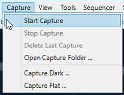
Start Capture
TheStart Capture menu item or toolbar button allows a custom capture limited either by number of frames or time to be started.
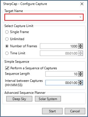
The Target Name box is highlighted in red if left blank to remind you to fill it in. If you enter text in the Target Name box then that text will be used as the target name for saved file naming purposes.
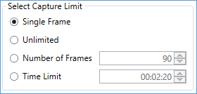
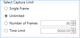
Capture Limits Explained
|
|
· Two files will be created – a single frame PNG, FITS or another selected still image format, together with the camera settings TXT. · Upon completion of the capture, information will be displayed in the Notification Bar. · The files will be stored in the default capture folder. |
|
|
· Two files will be created – an AVI or SER, together with the camera settings TXT. · Note if a still file format is selected in the ‘Output Format’ control, multiple still image files will be created in a single folder instead of a single video file. · Upon completion of the capture, information will be displayed in the Notification Bar. · The files will be stored in the default capture folder. · The capture will continue until the Stop Capture button in the tool bar is clicked. |
|
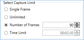
|
· Two files will be created – an AVI or SER, together with the camera settings TXT. · Note if a still file format is selected in the ‘Output Format’ control, multiple still image files will be created in a single folder instead of a single video file. · Upon completion of the capture, information will be displayed in the Notification Bar. · In this example, the capture file will contain 5 frames. · The files will be stored in the default capture folder. |
|
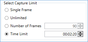
|
· A time limit can be set using HH:MM:SS. In this example 30 seconds is the limit set for the capture. · Two files will be created – an AVI or SER, together with the camera settings TXT. · Note if a still file format is selected in the ‘Output Format’ control, multiple still image files will be created in a single folder instead of a single video file. · Upon completion of the capture, information will be displayed in the Notification Bar. · In this example, the capture file will be a 30 second video. · The files will be stored in the default capture folder. |
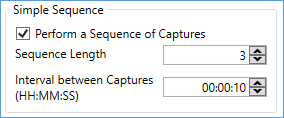
Performing Simple Sequences
|
|
· This repeats the capture defined in the capture limit section above. · Note this option cannot be activated when the capture limit set above is ‘Unlimited’. · A sequence of captures, with an interval between them, can be initiated. · In this example, 3 captures will be taken, with an interval of 10 seconds between them. · Six files will be created – 3 AVI or SER, together with 3 camera settings TXT. · Upon completion of the capture, information will be displayed in the Notification Bar. · In this example, the capture files will be a 3 x 10 second videos. · The files will be stored in the default capture folder.
|
Planning Deep Sky or Solar System Imaging Sessions
You can access a much richer variety of tools for planning an automated deep sky imaging session by clicking the Deep Sky button in the Advanced Sequence Planner section. This will launch the Deep Sky Sequence Planner. Similarly, the Solar System button will launch the Solar System Sequence Planner for planning automated planetary, lunar or solar imaging.
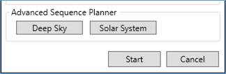
Starting the Capture
Once the capture options have been set, press the Start button to begin the capture or press the Cancel button to abort.
With large numbers of frames or extended time sequences it is advisable to use a guided telescope.
During a capture, the progress will be shown at the right-hand end of the Status Bar (bottom right of the screen).
![]()
Actual/Total frames and an estimated finishing time (ETA) are displayed for the duration of the capture.
When the capture is complete, information about the status, location and name of the captured file is displayed in the Notification Bar below the Tool Bar.
![]()
The blue text in the Notification Bar is clickable. If you click on the filename part (in the above example ‘20_42_24.avi’) then SharpCap will attempt to open the captured image or video for you, using your default viewing application for that file type. If you click on the folder name part, SharpCap will open that folder in Windows Explorer so that you can view the files in it.
Stop Capture
Once a capture has been initiated, the Stop Capture option becomes available – this will stop the current capture immediately. Note that pressing the <ESC> button on the keyboard will also stop any capture in progress.
Note that if a sequence of captures is in progress it will only stop the current capture, not cancel the sequence. The whole sequence can be cancelled using the Cancel button in the notification bar that appears while waiting for the next capture in the sequence.
![]()
If the delay between captures in the sequence is short, you may find it hard to press the Cancel button in time. In that case press and hold the <ESC> button until the capture is fully cancelled.
Quick Capture
Quick Capture is only available in the toolbar. Pressing the down arrow to the right-hand side of the button will show a list of quick capture options from 100 up to 5000 frames and 10 seconds up to 180 seconds. You can choose from one of these options and capture will start immediately.
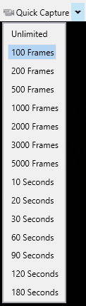
You can also just click the Quick Capture button – that will use the option most recently chosen from the dropdown list and begin capturing straight away.
Snapshot
Snapshot is also only available in the toolbar. Pressing the Snapshot button will capture a single frame and save it to a still image file. If a video capture file type is selected in the Output Format control then the preferred still file save format will be used instead.
![]()
If the camera is in Live Mode and taking relatively long exposures (more than about 2s), Snapshot will try to save the currently displayed image rather than waiting for the next image to arrive from the camera. However, it will wait for the next image to arrive under either of the following two conditions
1) Any camera controls have been changed since the current image arrived from the camera
2) The current image has already been saved using the Snapshot button
If the camera is in Still Mode then the Snapshot button will always start a new exposure and save the resulting image.
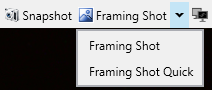
Framing Shot
Framing Shot is only in the toolbar and is only available when the camera is in Still Mode. Pressing the Framing Shot button causes the camera to capture a new image, but the image is only displayed on screen in SharpCap – it is not saved to file. This is useful to check that the target is in view and positioned correctly without creating saved image files that you will need to delete later.
For cameras that have a Gain control and where SharpCap understands the relationship between the gain value and the effect on image brightness, the dropdown next to the Framing Shot button will reveal the Framing Shot Quick option. A quick framing shot is taken by setting the camera to maximum gain, reducing exposure to compensate for the increased brightness, taking an exposure and then putting the gain and exposure back to their original values. This will create a noisier image, but will do so much more rapidly than a normal Framing Shot.
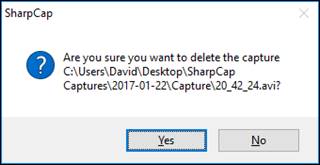
Delete Last Capture
Once a capture has been completed, the option to Delete Last Capture becomes available. A confirmation dialogue window is shown, which is useful if a capture is taken accidentally or if something goes wrong during a capture.
Open Capture Folder
Open Capture Folder opens a File Explorer window at the location where captures are currently being saved. In a default configuration, this would normally be:
Desktop\SharpCap Captures\YYYY-MM-DD
Capture Dark
This menu item launches the SharpCap dark frame capture assistant – see Capturing and Using Dark Frames.
Capture Flat
This menu item launches the SharpCap flat frame capture assistant – see Capturing and Using Flat Frames.
Camera Controls
Correctly adjusting the camera controls is essential for any type of imaging, and it is equally important to understand the function of the various controls in order to understand which adjustments are needed.
The various controls you might see for cameras that you use in SharpCap are listed below, separated into the control groups in which they will appear. Not all controls are available for all cameras – some are specific to certain brands of camera. Some controls only appear on a very limited range of cameras and will be covered in the separate *** Specialist Controls *** section.
Capture Format and Area
The Capture Format and Area control group typically contains controls that influence the size, bit depth and colour information of captured images, as well as the format of files that will be saved when capturing. In general, changing controls in this group (aside from the Output Format control) will restart the camera, causing imaging to pause and any capture or other action in progress may be stopped.
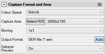
Colour Space
The colour space control determines the image format each frame is captured in. This includes choosing the bit depth to capture in where there are multiple choices available and whether to capture in colour or monochrome. In general, there are four categories of colour spaces :
· Monochrome
· Colour
· Raw
· Compressed
See Colour Spaces Explained for more detail on the colour space to choose and the implications of each choice.
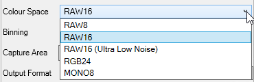
Some cameras may have additional colour spaces – for instance ‘RAW8 (slow)’ and ‘RAW8 (fast)’ or ‘MONO 16’ and ‘MONO 16 (Ultra Low Noise)’. In such cases, the image format is the same for the two options, but the camera may be set into a different operation mode, which may have effects on the data that it captures.
Capture Area
This controls the size (in pixels) of each frame captured. For most cameras, the choice of a smaller capture area selects capture of a subarea of the full sensor area – this is often termed ROI (region of interest) capture.
As well as giving smaller saved files, selecting a smaller capture area often gives a higher frame rate, providing the exposure time is short enough.
Many cameras offer the ability to select a custom capture area – there are two ways to activate a custom capture area :
·
Press the Select ROI button to the left of the dropdown
showing the possible capture areas. Once pressed, a red selection
box will appear over the image that can be moved and resized using
the mouse. The Select ROI button will change to Apply
ROI, and can be pressed to activate the new ROI once the
selection area is chosen. 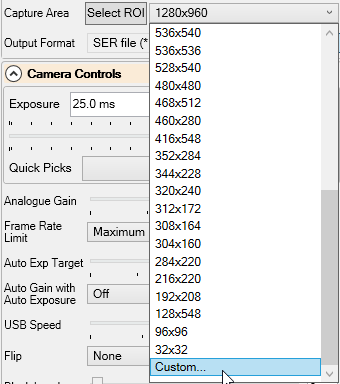
·
Choose the Custom… option at the bottom of the list of
available capture areas. This will show a separate window where you
can enter the width and height of the capture area that you would
like to use.
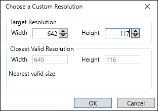
Note that many cameras have restrictions on the exact sizes that are allowed for capture areas – for instance that the height must be even, or the width must be divisible by 8. SharpCap will take these rules into account if appropriate and choose a valid capture area that is close in size to the one requested.
Resolution
This is an alternative to Capture Area that is used for Webcams (DirectShow cameras). The different name reflects the fact that most webcams do not change to a Region of Interest mode when a lower resolution is selected, instead they tend to provide the same image at a smaller resolution.
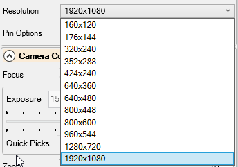
A small number of webcams (notably Microsoft branded ones) have a Zoom control – increasing that may enable an ROI mode when a smaller resolution is selected.
Region Of Interest Selection (Pan/Tilt)
When a camera is operating in Region of Interest (ROI) mode, SharpCap will show this control to allow you to move the ROI area around on the sensor.

The mid grey rectangle represents the whole of the sensor area, while the dark grey rectangle outlined in red represents the area currently being used for ROI capture.
You can adjust the position of the ROI area by dragging the dark grey rectangle around with the mouse, or by adjusting the values of the Pan and Tilt controls (Pan controls left/right position, Tilt controls up/down).
Moving the ROI rectangle in this way will not cause the camera to restart, but may lead to one or two glitched frames during or just after the movement.
If you click in this control to select it, then the ROI area can be moved around using the arrow keys on the keyboard. Each press will move the ROI area by 8 pixels in the appropriate direction.
Read Mode
Some cameras may offer a choice of read modes, which can be used to switch the camera between different operational modes. Read modes may allow for different interpretations of the camera’s resolutions, or different gain profiles or control other aspects of the camera.
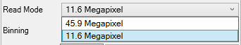
When the read mode is changed, the ranges or available values for other camera controls may also change.
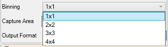
Binning
Binning is a technique used to improve the
signal-to-noise ratio of an image at the expense of reducing the
resolution. Binning works by taking the value of 2 or more
neighbouring pixels on the sensor and either adding or averaging
them to produce the value for a single output pixel. Binning
is usually 'symmetric' - meaning that the same number of pixels are
averaged over in each direction. For instance, a binning value of
'2x2' or just '2' means that a 2 by 2 block of sensor pixels are
used to make each pixel in the final image – this will reduce the
resolution of the final image by a factor of 2, but also increase
the signal-to-noise ratio (S/N ratio) of the image by a factor of
2.
As an example, with a 1280x960 sensor, using 2x2 binning will give
an output image of 640x480. Using 4x4 binning will give an output
image of 320x240.
A binning value of '1' or '1x1' means that no binning is being
applied.
Note: Most cameras will continue to display
the unbinned resolutions in the capture area control when binning
is applied. That is, a camera with a 1920x1080 sensor in 2x2
binning mode will continue to show capture areas up to 1920x1080,
but will capture at 960x540 due to the binning. However, Altair
cameras do the opposite – when binning is applied, the sizes shown
in the Capture Area control will drop to reflect the binned sizes
of the image.
Note: Some cameras add pixel values when binning (meaning that the
image will get brighter when binning is turned on), while other
cameras average the values (meaning that the image doesn't get
brighter, but the noise reduces instead). In both cases, the
same increase in S/N ratio is achieved in the final image – if a
brighter image is required and the camera averages then just turn
up the gain – the result being the same as if the camera had added
pixels.
Additive Binning
|
|
|
|
Unbinned (width 2x, height 2y) |
Binned 2x2 (width x, height y) |
Additive binning – no other changes were made to camera settings between the unbinned and binned images. Applying the 2x2 binning halves the size of the captured image and brightens the image by a factor of four. Note that a considerable level of noise is visible in the brighter right hand section of the image in both frames.
Averaging Binning
|
|
|
|
|
Unbinned (width 2x, height 2y) |
Binned 2x2 (width x, height y) |
Binned 2x2 with extra gain (width x, height y) |
Averaging binning – no other changes were made to camera settings between the unbinned and binned images. Applying the 2x2 binning halves the size of the captured image but does not brighten the image in this case. However, looking closely at the bright area on the right-hand side of the image shows that applying the binning has significantly reduced the noise in this area (and across the rest of the frame). Increasing the gain further does brighten the binned image producing a similar image to the additive binning result both in terms of image brightness and noise level.
Note that a small number of cameras may offer a Binning Mode control that allows you to switch between additive and averaging binning.
Output Format
Output format allows the choice of the format any captured files will be saved in. The options for capture format can be found in Capture Formats Explained. The following rules apply:
· For 'Snapshot' (single frame) captures, one of the still capture formats (PNG, FITS, TIFF and JPEG) are always used, even if the selected output format is a video format (AVI or SER). If the output format is a still file format, the selected format is used.
· For multi-frame captures, the selected format is always used. If a still file format is selected each frame will be saved to a separate file.
· If the camera is in Still Mode, video file formats will not be shown as options in this control.
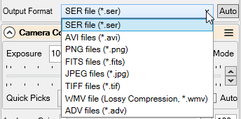
When the output format is set to ‘Auto’, a compatible video format is selected if the current exposure is less than 5 seconds and a compatible still format is selected if the current exposure is greater than 5 seconds. The preferred output formats specified in the settings dialog are used (providing the preferred format is compatible with the type of image being captured – for instance 16-bit depth images cannot be saved to AVI format). See the Saving Settings to adjust the preferred file formats for still and video captures.
Note: If the ‘Start Cameras with Auto Output Format’ option is checked in the Saving Settings then cameras will always start with this control in ‘Auto’ mode.
Debayer Preview
This control appears either when a RAW colour space is in use on a colour camera, or if a MONO colour space is in use on an ASCOM camera that claims to be monochrome.
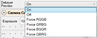
This control can be used to
· Turn off debayering of the displayed image in SharpCap by setting to Off. Doing this will display a monochrome image on screen in SharpCap that may have a grid pattern visible at the pixel level if the camera is a colour one.
· Correct the colour shown in SharpCap by choosing one of the Force XXXX options – this is useful if SharpCap incorrectly detects the bayer pattern of your camera and shows the image with incorrect colours.
· Apply debayering to get correct colours displayed when using a colour camera via ASCOM if the camera incorrectly identifies itself as monochrome by choosing one of the Force XXXX options.
In general, leaving this control set to On will be the correct setting for 99.9% of cameras.
Note that changing the setting of this control does not affect the image data saved to file (but does affect the file metadata for SER, ADV and FITS format – setting the correct debayer preview setting should help ensure that compatible processing applications automatically debayer the saved RAW files correctly).
The images below show two possible outcomes of an incorrect setting for this control (the images are zoomed considerably – the squares are individual pixels). On the left is a typical grid that will be seen when the control is set to Off for a colour camera in RAW mode. On the right is an example of choosing a Force XXXX option that is incorrect – in this case interpreting the values of red and blue pixels as green and vice-versa. The purple colour cast is typical of two of the three possible wrong Force XXXX settings – the final wrong setting swaps the red and blue colour channels, giving a more subtly incorrect image.
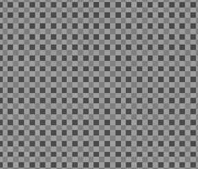
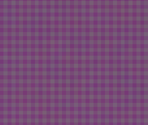
One good way to find the correct pattern for a camera in case of doubt is to shine a red light (red torch, LED, etc) into the camera, then try each pattern – the one that shows a red image rather than green or blue will be the correct setting.
Frames Per Second (FPS)
This control is only shown for webcams, and adjusts the maximum rate at which the camera will provide frames to SharpCap.
Note that setting a long exposure along with a high FPS value (for instance 0.5s exposure and 30fps) may have unexpected results – any of the following may happen, depending on the exact webcam in use:
· The frame rate may reduce - to approximately 2 per second in the example given
· The exposure selected may not actually be applied – in the example, the frame rate may stay at 30fps and the exposure may really only be about 1/30s
· The frame rate may stay at 30fps, but while 30 frames per second are being processed, the image may only change about twice per second.
Pin Options
This control is only shown for webcams. It provides access to a separate window of camera settings that can be adjusted. The content of this window is provided by the webcam driver, not by SharpCap. You may be able to use the Pin Options window to make adjustments to the camera settings that are not possible in SharpCap. SharpCap will pause the camera while the Pin Options window is visible, and restart it with any changes applied when you close the Pin Options window.
![]()
Camera Controls
The camera controls are the primary controls for setting up the camera, and includes key controls such as the length of the exposure and the camera gain.
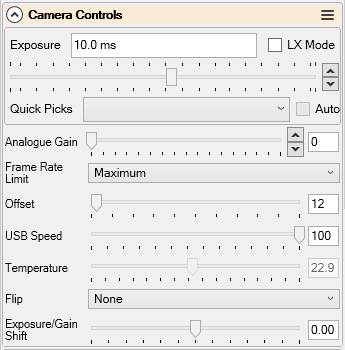
In general, adjusting controls here will adjust the way that the hardware of the camera works, rather than applying digital processing to the image that has been captured (controls in the Image Controls section are usually related to digital adjustments to the image).
Exposure
The Exposure control is one of the key controls for configuring the camera – it controls the length of time that the camera collects photons for each frame. Almost all cameras (with the exception of frame grabbers and a few webcams) will have an exposure control that you can adjust.
Setting longer exposures allows more photons to be collected during each frame, and will give brighter images. Conversely, setting shorter exposures will give darker images.
Since setting the exposure is so important, the exposure control has more functionality than most controls in SharpCap
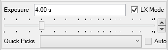
Things to note about using the exposure control:
· The ‘LX Mode’ checkbox does nothing to the camera, but it changes the range of the slider from short exposures (up to 5s) with the box unchecked to long exposures (1s and up) with the box checked.
· You can type an exact exposure that you want into the numeric display box – something like ’10.5s’ or ‘30ms’ or even ‘5m’. If you just put ‘5’, it will be treated as 5s.
· You can pick from the list of commonly used exposures in the ‘Quick Picks’ dropdown
· Clicking to the left of the slider halves the exposure, clicking to the right will double the exposure.
· The up and down arrows to the right of the slider change the exposure up/down by approx. 2% for each click
· For most cameras, if the ‘Auto’ exposure mode is enabled the currently set auto exposure will be displayed and updated from time to time. Note that not all cameras support an auto exposure setting.
The limits on minimum and maximum exposure available are determined by a combination of the camera hardware and the device driver/SDK software written by the camera manufacturer. SharpCap does not apply its own limits on minimum or maximum exposure.
A particular exposure value will place a limit on the maximum frame rate that a camera can achieve – for instance if the exposure is set to 200ms, no more than 5 frames per second are possible. If the exposure is reduced to 20ms then – in theory – up to 50 frames per second are possible. Of course there are other limits such as the maximum speed the camera sensor can take images and the rate at which image data can be transferred to the PC that may prevent 50 fps from being achieved.
When using longer exposures in live mode, SharpCap will try to cancel the current frame in progress and start a new frame when the exposure control is adjusted. For instance with the exposure set to 30s, you decide to increase it to 60s. SharpCap will try to cancel the current 30s frame in progress and start a new 60s frame as soon as possible. Depending on the camera, the cancelled frame may be stopped early and displayed rather than discarded.
When using still mode, it is best to avoid changing the exposure while a frame is being captured.
Gain or Analogue Gain
The Gain control is probably the second most important control in the Camera Controls group. It acts a bit like a volume control for the image brightness. Setting it to higher values increases the brightness of the image (for the same exposure time and amounts of illumination). Importantly, the effects of this control are applied before the ADC (analogue to digital conversion) stage of image processing, meaning that setting higher gains can have some beneficial effects in reducing the inherent read noise associated with each frame. Paradoxically, in spite of potentially lowering one sort of noise, increasing gain makes images noisier because it magnifies the other sort of noise (shot noise) associated with capturing photons.
Since fine adjustments to the gain value can be important to getting good images, SharpCap includes a pair of up/down buttons to the right of the slider, which will change the gain value by about 2% (or 1 unit if 2% is smaller than 1 unit).
![]()
Note : Cameras that use CCD sensors may not have an adjustable gain control. While almost all CMOS cameras have a gain adjustment, some webcams may not make the gain available for adjustment. For DSLR type cameras, the ISO reading in use is effectively the gain, and this may be shown as a dropdown of available options rather than a slider control.
What does a gain value mean?
For many dedicated astronomy cameras that are directly supported, SharpCap understands the relationship between the gain value (the number displayed next to the slider) and the effect on the image brightness. If this is the case then hovering the mouse over the slider will show a tooltip containing information about how the gain is affecting image brightness.
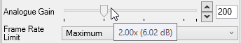
In the example above, the tooltip of ‘2.00x (6.02dB)’ indicates that the gain value of 100 is causing the image to be 2.0 times brighter than it would be at minimum gain, which is a brightness increase of 6.02dB (decibels – an increase of 20 decibels is the same as making the image 10 times brighter).
Support for showing this information varies by camera brand and model as detailed below
|
Camera Brand |
Gain Brightness Info Available |
Gain Value Measured In |
|
Altair |
Yes |
% of minimum gain |
|
AstcamPan |
Yes |
0.1 dB |
|
AstroAsis |
Yes |
0.1 dB |
|
Atik |
No |
Unknown |
|
Basler |
No |
Unknown |
|
Celestron/Imaging Source |
No |
Unknown |
|
Moravian Instruments |
Yes |
1 dB |
|
Player One |
Yes |
0.1 dB |
|
Point Grey (FLIR) |
No |
Unknown |
|
QHY |
Some Models |
0.1 dB or 1dB or Unknown |
|
StarlightXpress |
No |
Unknown |
|
SVBony |
Yes |
0.1 dB |
|
ZWO |
Yes |
0.1 dB |
|
ASCOM Cameras |
No |
Unknown |
|
DirectShow/Webcams |
No |
Unknown |
The last column in this table shows how the gain value translates into brightness changes – where this information is known. For many cameras the gain value indicates either the brightness increase in dB (starting from zero for minimum gain, with a range maybe up to 30 to 60) or in 0.1dB (starting again from zero ranging up to perhaps 300 to 600 depending on model). For Altair cameras, minimum gain is 100 and the brightness increase is 2 for 200 gain, 4 for 400 gain, etc.
Note that for cameras where gain/brightness information is unavailable, some other features such as the Exposure/Gain Shift control and Framing Shot Quick will not be available.
R/G/B Gain
A small number of colour cameras have separate gain adjustments for the red, green and blue colour channels. Where present, these will show as separate red, green and blue gain controls. Note that these differ from the standard red/green/blue white balance controls that appear for many other cameras – R/G/B gain is applied before analogue to digital conversion, whereas R/G/B white balance is applied by adjusting the digital data after conversion.
Digital Gain
Some cameras will offer a digital gain control, either on its own or in addition to a normal analogue gain control. Digital gain is applied by multiplying pixel values up by some amount. Although best left set to minimum when capturing images for later processing (as it damages data by making some non-saturated pixels saturated), digital gain can be useful when using shorter exposures to find targets, assist focusing, etc.
Black Level/Offset
This is another important control for astro imaging. Adjusting this control sets the average pixel value that will be produced by the camera for a black pixel (one with no light falling on it during the exposure). Because there are random fluctuations in the electronics of any camera, even when taking an exposure with no light at all, some pixels will have values below this average level by a bit and some a bit above it. This random spread of values becomes larger as the gain is increased.
Note that some cameras name this control as Offset and some as Black Level. For historical reasons, ZWO cameras call this control Brightness and appears in the Image Controls group. Regardless of name, the effects and procedure to properly set the control are the same.
The value of this control should be adjusted with reference to the Histogram tool, looking at the histogram produced with no light entering the camera and the gain set to the value to be used for imaging.
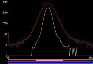
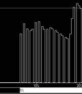
The image below shows a typical histogram for dark frames for low gain, with a narrow peak that is well separated from the left hand side of the graph. In particular, there are no pixels with zero value. In this case the Offset control could be lowered to move the histogram peak left, closer to (but not touching) the left hand side of the graph.
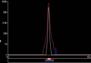
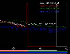
The second image below shows how the histogram changes when a medium gain is selected – giving a broader peak. Looking at the individual red/green/blue lines, you can see that there are a few pixels with zero value, but not many (maybe less than 100 of each colour out of a total of ~ 2 million). In this case the Offset value is roughly optimal – it could be increased slightly to reduce the number of pixels that have zero value, but the practical effects of any increase would be very small.
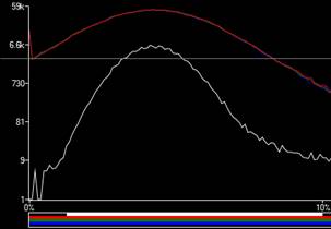
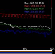
Finally, the third image below shows how the histogram spreads further for a high gain value. You can now see that there are tens of thousands of pixels of each colour that have zero value. This indicates that the value of the Offset control should be increased to move the histogram peak to the right, away from the left hand side of the graph.
The reason that it is important to keep the histogram for dark frames clear of the left hand edge of the graph is as follows : If a significant number of pixels have zero value, then – due to the random spread of pixel values seen in the graphs – some of those with zero value would really have measured as negative values if negative values were possible. Since negative values are not allowed, those pixels get the value zero, which is a bit higher than the value should be for those pixels. When you capture lots of frames and average them together, the average will be increased a bit because of the pixels that had their values boosted up to zero, and because of that you will either have dark frames that overcorrect somewhat or light frames that have some extra unnecessary background.
Having the Offset control set too high has the small negative effect of limiting the amount of pixel brightness range between the black point and the maximum pixel value – i.e. reducing the available dynamic range of each frame a little.
Exposure/Gain Shift
This control is implemented by SharpCap and appears for cameras where both an exposure and gain control are available and SharpCap understands the relationship between the gain value used by the gain control and image brightness.
![]()
The control adjusts both the exposure and the gain at the same time in a way designed to keep the image brightness constant. For every unit the control is moved to the right, the exposure will double, but the gain will be adjusted to halve the image brightness to compensate. For every unit the control is moved to the left, the exposure will halve, but the gain will be adjusted to double the image brightness to compensate.
The main use of this control is to quickly move between camera settings aimed at deep sky capture (long exposures, relatively low gain) and settings suitable for focusing, plate solving or framing images (shorter exposures, high gain to keep the target visible).
The limits of this control depend on how much adjustment is available on exposure and gain in the direction required – for instance if your camera is already at minimum gain, you will not be able to move this control to the right at all, since there are no lower gain values to adjust to. The maximum possible range is between -6 (1/64th exposure, gain making the image 64 times brighter) and +6 (64x exposure, gain reduced to make the image 64 times dimmer).
Note that if you make a separate adjustment to either the exposure or the gain controls then this control will reset to zero – allowing you to make adjustments based on your new basic exposure/gain settings. This control will be disabled if either the exposure or the gain are set into Auto mode.
Frame Rate Limit
This control is implemented by SharpCap for all cameras, and does not affect the hardware of the camera. Instead, it limits the rate at which SharpCap will accept frames from the camera to (roughly) the set value.
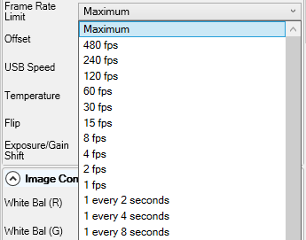
The camera will still be capturing images at the normal rate, but if this is set to ‘2 fps’ then SharpCap will only select 2 of those images every second to display and save (if currently saving images) – any extra images are discarded.
This feature can be useful to limit the rate at which frames are captured to a video file, for instance for time lapse imaging or all sky cameras.
Note that the timing between selected frames will not exactly match the rate specified by this control.
USB Speed/Turbo USB
Many CMOS cameras allow a USB Speed or Turbo USB control to be adjusted. This control adjusts how hard the camera tries to push image data over the USB connection as fast as possible.
![]()
Setting a high value gives the potential for achieving maximum frame rates for high speed imaging, whereas setting a low value tends to improve reliability and stability and may be best when the frame rate is not important (i.e. when using long exposures).
Under some circumstances, a value that is set too high can lead to any of the following symptoms :
· Frame rates dropping to very low levels
· No frames at all coming from the camera
· Other errors in communication with the camera
If these symptoms are observed, setting this control to a lower value is a good first troubleshooting step to see if the problem is resolved.
USB Traffic
This control is available for QHY cameras as an alternative to USB Speed or Turbo USB. It has exactly the same behaviour as those controls except that the values are reversed – set the lowest value to try to achieve the maximum frame rate and set higher values to increase stability.
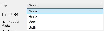
Flip
The Flip control is provided by some cameras and allows the orientation of the image to be altered – flipped in either the horizontal, vertical or in both directions.
This control should be used with extreme caution, since when changed from None, the you must take care to
· Deal with changed bayer patterns for RAW colour images in processing software
· Only use dark and flat frames that have been captured with the same Flip setting. Using dark or flat frames captured with a different Flip setting will give incorrect results
It is typically better to use the Flip (after dark/flat) control in the Preprocessing group – this is provided by SharpCap for all cameras and flips the image after SharpCap has applied dark and/or flat correction.
Note : Some cameras provide separate controls to turn horizontal and vertical flip on and off.
Auto Exposure Target
This control sets the brightness level (out of a maximum of 255) that the camera auto exposure will aim for. It has no effect when the camera exposure is set to manual mode.
Auto Gain with Auto Exposure
This control, only available on Altair cameras, configures whether the camera can automatically adjust gain when auto exposure is enabled, and if so, how high a gain value can the camera use.
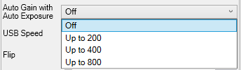
The control has no effect when camera exposure is set to manual mode.
Hardware Binning
This control, available on ZWO cameras, sets whether binning calculations are performed in hardware on the camera (set to On) or in software on the computer. Under some circumstances, setting this to On when using binning may increase the maximum frame rate. The control has no effect on image quality.
High Speed Mode
Some cameras (typically ZWO models) may offer a High Speed Mode control, which can be turned on or off. This control typically only has an effect when the camera is in an eight bit mode. Turning the High Speed Mode control to on may allow higher frame rates to be achieved, but may have the side effect of changing the image brightness and increasing the amount of noise visible in the image.
Temperature
Some cameras do not have a cooling system, but have a temperature sensor which measures the temperature of the imaging sensor inside the camera. For such cameras, a temperature control may be visible inside the Camera Controls group, which will show the current temperature reading of the camera. This will be a read-only control – it cannot be adjusted. The value will typically update every few seconds, but for some camera models it may only update once per frame.
Fan
A small number of cameras may contain a cooling fan, but no thermoelectric cooler. If the fan can be adjusted then a Fan control may be shown to allow the fan to be turned on or off or the speed to be adjusted. Note that for cameras that have a thermoelectric cooler, the Fan and Temperature controls will appear inside the Thermal Controls group.
Focus, Zoom (Webcams)
DirectShow cameras (Webcams) may offer Focus and Zoom controls in the Camera Controls group, if the camera hardware supports those actions. The Focus control will typically adjust the focus of the built in Webcam lens and may offer an automatic as well as a manual option. The Zoom control is unlikely to actually adjust the zoom lens attached to the Webcam – it is more likely that it adjusts a digital zoom effect that allows the image to zoom in on a section of the entire camera frame. When combined with choosing a lower than maximum resolution, the zoom control may make it possible to achieve ROI mode using a Webcam.
Byte Swap 16 bit data (PGR)
This control may be shown for Points Grey cameras – it offers to the ability to adjust how SharpCap interprets the data from the camera when the camera is running in a 16 bit mode. If the image from the camera appears incorrect when running in 16 bit mode, try adjusting this control to the opposite setting, which should correct the image. Unfortunately it seems to be impossible to autodetect the correct setting for this control from the camera SDK.
Image Controls
The Image Controls group mainly contains controls that affect the adjustments applied to the image after it has been captured by the camera sensor. Most of these adjustments are applied by adjusting the digital pixel values of the image according to some appropriate calculation. These adjustments are carried out in the camera software provided by the camera manufacturer, and are applied to the image data before the data reaches SharpCap. This means that it is very likely to be impossible to accurately undo the effects of these adjustments if you later decide that they were applied incorrectly.
For instance a control that adjusts the blue component of the image to give white balance adjustment (White Balance(B) or WBB) is likely to do so by multiplying all the pixel values for blue pixel data by some factor – perhaps 1.3 if the control is set to 130. One effect of this adjustment is that all pixel values higher than 196 will be set to the maximum pixel value of 255 (for 8 bit data). Any information in the image in that pixel range between 196 and 255 for blue pixels is lost and can never be recovered.
Given the above, you may wish to avoid using these controls, and leave them in their ‘neutral’ positions. This allows the unmodified data from the camera sensor to be received by SharpCap and saved to file. Adjustments for colour balance and other image adjustments can then be applied after processing and stacking, meaning it is always possible to go back to the original data and try again if the initial settings don’t work exactly as you had hoped. On the other hand, many people successfully produce great images by using these controls to adjust the colour balance and other aspects of the image before stacking, so both approaches are possible.
It is usually possible to work out the ‘neutral’ value for these controls by observing the image histogram while displaying a terrestrial image (not an astronomy image) and adjusting the controls. The histogram graph will usually show artefacts such as gaps in the graph, failing to reach the right-hand side even when well exposed, or crenelation features when these controls are set to values that cause them to make an adjustment to the image data. These effects disappear when the controls are set to the neutral value.
The images below show, from left to right:
· the red channel failing to reach the right-hand side of the histogram due to a white balance adjustment that is reducing the amount of red in the image.
· the red channel showing crenalation features due to a white balance adjustment that is increasing the amount of red in the image.
· The histogram of a monochrome camera showing gaps due to the use of a gamma adjustment control.
Note that for some models of camera, the controls in this group will be unavailable or disabled if the camera is in a RAW mode. If you wish to use these controls find them a thing or disabled for your camera, try putting the camera into an RGB mode via the Colour Space control.
Digital Processing (on/off)
Some cameras (notably Altair models) have this control as a master switch which can be used to turn on or off the remaining digital image processing controls in the group. Setting this control to Off ensures that digital processing is not applied and may lead to small reductions in CPU usage or small improvements in camera frame rate.
Negative
This control, when enabled, will invert the image in the manner of a photographic negative – making the brightest areas of the image dark and the darkest areas of the image bright, both on screen in SharpCap and in saved files. When applied to a colour image, the effect is applied to each of the three colour channels separately.
Contrast
This control adjusts the contrast of the image – setting higher values will increase the contrast by making the bright areas brighter and the dark areas darker. Conversely, lower values will decrease the contrast by making bright areas darker and darker areas lighter. Very low values may give a uniformly grey image.
Brightness
This control adjusts the brightness of the image – setting a higher value will make all areas of the image brighter by a uniform amount. For ZWO cameras, this control acts as the offset or black level control for the camera and should be adjusted according to the instructions given for the Black Level/Offset control in theCamera Controls group.
Gamma
This control will adjust the gamma of the image. Usually a neutral gamma which will have no effect has a value of one, but some cameras may use an alternative scale where the default neutral gamma has a different value like 100.
Correctly interpreted, gamma of less than 1 will boost the shadows and mid tones, gamma greater than 1 will lower the mid tones and highlights. Some applications and cameras treat gamma the opposite way around – increasing gamma boosts the shadows.
In most cases it is best to leave the gamma control at its default, neutral, setting. A better alternative to bring out hard to see detail in the image is to use the display stretch functionality built into the mini histogram. This allows the image has displayed on-screen in SharpCap to be adjusted without making any changes to the data saved file.
White Balance R/G/B
Colour cameras may offer White Balance controls (sometimes called colour balance) to adjust the colour of the image and allow any unnatural colour cast be removed. Depending on the brand of camera being used there may be three white balance controls for adjusting the strength of the red, green and blue channels or only two controls that allow the red and blue channels to be adjusted. In the latter case the green channel cannot be adjusted directly but the same results can be achieved via adjustments to the red and blue channels. Note that many cameras do not offer colour balance adjustments when the camera is operating in RAW mode.
For each white balance control, increasing the value will brighten the associated colour in the image, whereas reducing the value will darken the associated colour. For instance, for an image that has a green colour cast you might either decrease the green control or increase both the red and blue controls to give the image neutral colours.
If you decide to use the white balance controls to adjust the colour balance of the image, a good way to achieve accurate results is to point the camera at a white piece of paper and the sunlight and adjust the exposure so that the images unsaturated, then adjust the white balance controls to give a uniform light grey image.
Some models of camera may have an automatic white balance option – either with auto options which can be enabled for continuous automatic white balance or a separate Adjust button, which when pressed will auto adjust the white balance once based on the image currently being captured by the camera. Note that while auto white balance often works well for ordinary images but can sometimes be confused by astro images, so should be used with caution.
Note that the default, neutral, value for white balance controls varies depending on the make of camera and sometimes four different models made by the same manufacturer. Notably for ZWO cameras, the default neutral value is 50.
Timestamp Frames
This control is provided by SharpCap for all cameras, and offers the option to add a timestamp to the top left-hand corner of the image on each frame that is captured from the camera. For most cameras, the timestamp represents the time according to the PC’s clock at the moment that the frame was delivered to SharpCap. This will actually be some point after the end of capturing the frame – the difference being determined by how long the frame takes to be transferred from the camera to the PC and how long the camera manufacturers software running on the PC spends dealing with the frame before handing it SharpCap.
Note that the size of the font used to add the timestamp to the image can be adjusted in the Camera Settings page of the SharpCap settings.
Colour Temp and Colour Tint
Colour Temperature and Colour Tint controls provide alternative way of adjusting the colour balance for some cameras, notably Altair colour models. These controls are unavailable when the camera is in RAW mode, so adjusting them is rarely necessary for astro-imaging purposes.
Lowering the colour temperature tends to make the image bluer, while raising it will tend to give the image a more yellow/orange cast. For the Colour Tint control, lower values shade towards pink while higher values shade towards green.
An automatic white balance Adjust button may be available to auto set these controls, although the auto set values are not reflected in the slider positions after automatic adjustment.
Saturation
The Saturation control adjusts the amount of colour in the image. Setting lower values will make a colour image tend towards greyscale, while setting higher values will exaggerate the strength of the colours within the image.
For many cameras the Saturation control is unavailable when the cameras operating in RAW mode, and therefore this control need not be adjusted for most Astro-imaging uses.
Hue
This control typically adjusts the colour of the image by shifting colours around a colour wheel – for instance green becomes blue, blue becomes purple, purple becomes pink and so on. This control is usually best left at the default neutral value.
Sharpness
Some Webcams may offer a sharpness control which can be used to digitally enhance the sharpness of the image. Setting higher values will typically increase the sharpness of the image but may also increase the noise level visible in the image.
Backlight Compensation
Some Webcams may offer a backlight compensation control, which can help deal with situations where the foreground of the image is less well illuminated than the background (for example, someone sitting with a window behind them). This control is not normally useful for astro-imaging.
Filter Options
This control is only shown for webcams. It provides access to a separate window of camera settings that can be adjusted. The content of this window is provided by the webcam driver, not by SharpCap. You may be able to use the Filter Options window to make adjustments to the camera settings that are not possible in SharpCap.
![]()
Thermal Controls
The Thermal Controls group appears for cameras that have an active cooling system that can be controlled by SharpCap. These cameras will almost always need a separate 12V power supply to power the cooling system – without power the thermal controls may be adjusted but will have no effect.
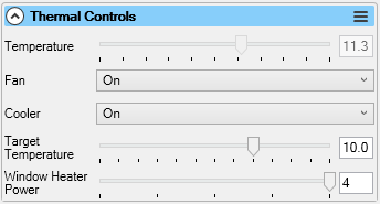
In addition, when the camera has a cooler, a summary of the cooler status will be shown in the status bar, showing the current cooler power level, current temperature and target temperature.
![]()
Cooler on/off
Certain cameras provide a master ‘on/off’ switch for the cooler – switching this to Off will turn off the camera cooler and disable other cooling related controls.
Fan
Some cameras allow adjustment of the fan independently of the cooling system. If that is possible then the fan may be turned on or off, or the speed adjusted by using this control. If the cooler is active, it is recommended to have the fan switched on and set to the maximum speed, otherwise cooling may not function or the performance may be poor.
Temperature
Almost all cooled cameras have a temperature sensor which measures the temperature of the imaging sensor inside the camera. This control show the current temperature reading of that sensor. This is a read-only control – it cannot be adjusted. The value will typically update every few seconds, but for some camera models it may only update once per frame.
Target Temperature
Most cooled cameras allow a target temperature to be set. The camera will then automatically adjust the cooler power to try to keep the sensor at the target level.
With modern CMOS cameras, keeping a constant temperature (even if not particularly cold – perhaps -5 to +5C) is more important than trying to get the sensor to the coldest possible temperature. It’s best practice to ensure that dark frames are taken at the same sensor temperature as light frames.
Depending on how the camera handles changing cooler power, it may take several minutes to adjust to a change in target temperature. The Deep Sky Sequence Planner and Sequence Editor can be used to carry out staged cooldown and warm up, if desired.
Cooler Power
Some cameras allow manual adjustment of the cooler power level. If there is also a Target Temperature control then set this control to Auto to enable automatic cooler power and the use of the Target Temperature control. When this control is set to manual, the Target Temperature will be ignored.
Window Heater Power
Cooled cameras may have a separate heater which warms the optical window covering the sensor. This warming can help avoid dew on the window as the camera cools in humid conditions. This control allows the power of the window heating element to be adjusted.
Pre-Processing Controls
Information on using the controls in this group can be found in the Image Processing in SharpCapsection.
Display Histogram Stretch
Information on using this control can be found in the Display Stretch section.
Scope Controls
Information on controlling telescope mounts and other hardware using the controls in this group can be found in the Telescope Hardware Control section.
Camera Specific Controls
The controls listed below will appear in addition to the common controls listed above.
Altair Camera Controls
SharpCap supports all current models of camera produced by Altair Astro. If the camera is a new model and not in the Cameras list, please check for an updated version of SharpCap which may include changes needed to support the camera.
Further information can be found at the Altair Astro website. Drivers, software and technical notes can be found at the Altair Support website.
There are no special controls for Altair cameras.
ASCOM Camera Controls
ASCOM cameras have relatively few controls available in SharpCap. Drivers and further information can be found at the ASCOM Standards website.
There is no guarantee all ASCOM cameras will offer all the controls listed below. For instance, some ASCOM cameras have no cooler at all and of those with coolers some may offer direct control of cooler power while others may not.
|
Camera Controls |
|
|
Options |
Allows the ASCOM configuration dialog for the camera to be shown. May have additional camera options that can be configured. The camera is temporarily closed while the dialog is displayed and will restart when it is closed. |
AstcamPan Camera Controls
You can find driver downloads and other information about the cameras on this website : here.
There are no special controls for AstcamPan cameras.
Atik Camera Controls
SharpCap supports most Atik camera models. You must install the latest Atik core software otherwise SharpCap may be unable to detect or control your camera.
|
Camera Controls |
|
|
Preview Mode |
Available on some cameras – when enabled the readout time of the camera may be decreased at the expense of reduced image quality. Enabling Preview Mode may be useful for framing and focusing, but it should be disabled for capturing images. |
|
Capture Dark Frames |
Only available on cameras with a physical shutter. When enabled the shutter will not open when taking an image, allowing dark frames to be captured without needing to cover the telescope aperture. |
|
High Speed Mode |
Available on some CMOS cameras – putting the camera into high speed mode will increase the frame rate, which may be useful for solar/lunar/planetary imaging. High Speed Mode should be disabled for deep sky imaging or live stacking. |
|
Image Controls |
|
|
Digital Gain |
Available for CCD cameras that do not have an analogue gain control. Digital Gain artificially brightens the image by enhancing the brightness of each pixel by multiplying it by the digital gain factor. This can be useful to allow shorter exposures for focusing, framing, etc., but should be disabled when capturing images. |
Basler Camera Controls
Drivers and further information can be found at the Basler website.
Basler Specific Controls
|
Capture Format and Area |
|
|
Colour Space |
Basler cameras use non-standard colour space names for RAW modes. · BayerBG8 – equivalent to RAW8 with BGGR Bayer pattern. · BayerRG12 – equivalent to RAW12 with RGGB Bayer pattern. · Bayer GB12Packed – equivalent to RAW12 with GBBR Bayer pattern. In packed 12 bit modes, 2 adjacent pixels are packed into 3 bytes (1.5 bytes each) rather than requiring 2 bytes each in unpacked mode. This may increase frame rates in some circumstances as it reduces the amount of data that needs to be transferred from the camera to the computer. |
|
FPS |
The number of frames per second that the camera will attempt to deliver to the computer. When left on auto it will aim for the maximum possible rate. Note that the frame rate set in manual mode may not actually be achieved due to factors such as the exposure being too long or the data rate between the camera and the computer being insufficient to cover the desired frame rate. If aiming for a limited frame rate, then setting this to a low value is better than leaving this at a high value and setting the 'Frame Rate Limit' control as it should reduce the CPU load on the capture computer. |
|
Camera Controls |
|
|
Black Level |
Allows the black level to be adjusted. This control should be adjusted with the camera covered to ensure that both sides of the black level peak in the histogram are visible and distinct from the zero level to ensure that black level noise can be averaged out correctly in stacking. Called offset or brightness on some other cameras. |
|
Digital Gain |
An additional gain that can be applied to the image. Each step above zero doubles the image brightness but also doubles the noise levels |
Celestron/Imaging Source Camera Controls
SharpCap should support all Celestron branded Skyris and NexImage cameras (manufactured by The Imaging Source) as well as Imaging Source branded DMK and DFK cameras.
Drivers and further information can be found at the Imaging Source website and the Celestron website.
|
Camera Controls |
|
|
Focus |
Controls the focus of the built-in camera lens (if available). |
|
Iris |
Controls the aperture of the built-in camera lens (if available). |
|
Pan, Tilt and Roll |
Physical controls to pan, tilt and roll the camera if it has motor drive to allow it to be controlled remotely. |
|
IR Cut Filter |
Turn on/off the IR cut filter on cameras equipped with a controllable filter. |
|
Image Controls |
|
|
Colour Enhancement |
Enhance colours in the image. |
|
Highlight Reduction |
Reduce the relative brightness of the highlights in the image. |
|
Denoise |
Apply a noise reduction filter to each frame (will also tend to reduce detail). |
|
Colour Enable |
Switch colour cameras between colour and monochrome mode. |
|
Sharpness |
Apply a sharpening filter to each frame to enhance detail (will also tend to increase noise). |
Moravian Instruments Camera Controls
SharpCap supports CMOS Moravian Instruments cameras. CCD based cameras may also work.
Drivers and further information can be found at the Moravian Instruments website.
CMOS cameras may have additional choices for the colour space options – for instance
· RAW8 slow
· RAW8 fast
· RAW12 slow
· RAW12 fast
The ‘fast’ modes may give higher frame rates. Other read modes may be available depending on the model of camera.
Player One Camera Controls
SharpCap supports the full range of Player One cameras.
Drivers and further information can be found at the Player One website.
Player One cameras currently do not have any specialized controls.
Point Grey Camera Controls
SharpCap supports FlyCapture based Point Grey cameras. Spinnaker based cameras are not supported. USB, GigE and Firewire models are all supported.
Drivers and further information can be found at the Point Grey website (Point Grey is now part of Teledyne Flir)
Note that you may need to restart SharpCap to detect GigE cameras if they are connected after SharpCap has been run.
There are no special controls for Point Grey cameras.
QHY Camera Controls
SharpCap supports a wide range of QHY CMOS cameras. The cooling features of the QHY ColdMOS cameras are supported as well as the GPS features of the QHY174-GPS. Older QHY CCD cameras may not work correctly (but may be usable via their ASCOM drivers).
Drivers and further information can be found at the QHY website.
|
Camera Controls |
|
|
Amp Noise Reduction |
This control is available for some cameras and when activated will reduce the amount of amp glow created by the camera for long exposures.
In general, it is best to leave this control on the 'Auto' setting as it will apply the amp glow reduction when appropriate. If amp glow reduction is enabled manually, this may result in incorrect images for certain exposure and gain combinations. |
|
Row Noise Reduction |
This control is available for some cameras and can be adjusted to reduce banding effects between camera rows. |
|
Use DDR Buffer |
Available on some cameras. Turns on/off the use of the internal DDR buffer on the camera. Using the DDR buffer may improve frame rate and reduce problems with dropped frames. |
|
Optimize Light Level |
Allows the sensor on the camera to be optimized for low or bright light levels. |
|
Filter Wheel |
Allows a QHY filter wheel connected via the camera port to be controlled. Note that a connected filter wheel may not be detected if it is still initializing when the camera is opened in SharpCap. |
|
Enable Live Broadcast |
Enable live broadcast of the images being shown in SharpCap via the QHY video broadcast application. |
|
GPS Controls |
|
|
GPS |
Enable or disable the built-in GPS functionality on cameras that support it. The GPS feature allows frames to be timestamped precisely to microsecond precision. GPS may require the camera to be supplied with 12V power. When GPS is enabled and has a satellite lock the timestamp for each frame taken from the GPS system is used for the timestamp in capture settings files and SER file frame timestamps. Without further adjustment, frame times will be accurate to millisecond levels, but to get microsecond precision the following controls must be adjusted correctly. |
|
GPS Calibration LED |
The GPS calibration LED must be turned on to be able to correctly adjust the following two controls. The camera must also be covered so that the light from the LED can be seen in the image. Turn up the gain so that the light can be seen easily. |
|
Calibration Start Pos |
With the GPS LED on, turn the calibration Start Pos down to zero and then turn it up until the calibration light appears as a glow at one side of the image. Then turn the value down a small amount until the light vanishes again. Setting this control allows the GPS frame start time to be corrected for the time difference between the camera circuitry requesting the frame starts and the actual exposure starting. |
|
Calibration End Pos |
With the GPS LED on, set this to a value just above the calibration Start Pos value and then turn up the value until the LED light vanishes again. Turn the value down a small amount until the light re-appears. This allows the end of frame time to be adjusted for the time difference between the camera circuitry requesting the frame to stop and the frame having finished.
After calibrating the Start and End Pos, don't forget to turn the calibration LED off again. Also, note that the calibration needs to be repeated after having changed the camera exposure or the camera colour space. |
Starlight Xpress Camera Controls
SharpCap supports the full range of StarlightXpress CCD cameras. Drivers and further information can be found at the Starlight Xpress web site.
Capture Format and Area
Some Starlight Xpress cameras have interlaced sensors, meaning that only half of the lines on the sensor can be read at a time. When a camera with an interlaced sensor is in use, SharpCap adds an Interlace Handling control to allow various ways of dealing with the interlaced camera to be chosen.
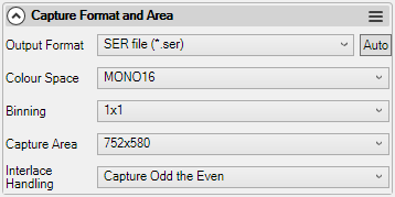
The options for Interlace Handling are
· Capture Odd then Even Rows - this option will expose the camera twice for each frame shown in SharpCap, first capturing the odd lines of the sensor, then the even. This is the only option that gives full sensor resolution, but frame rate is halved (for instance with a 2s exposure selected, the image will only update once every 4s)
· Interpolate from Odd Rows – this option will only expose the odd rows of the sensor, but will generate a full-size image by generating data for the even rows by averaging (interpolating) the data of the odd rows on either side. Frame rate will be normal, but there will be less detail in the image
· Interpolate from Even Rows – as Interpolate from Odd Rows, but exposes only the even rows of the sensor, with the odd rows being generated by averaging
· Capture Odd Rows – exposes the odd rows of the sensor and forms an image only half the normal height (290 pixels for the camera shown above). Frame rate will be normal, but images will be distorted due to halving the height of the image
· Capture Even Rows – as Capture Odd Rows, but captures only the even rows.
· Capture All Rows (2x vertical bin) – this option exposes all pixels on the sensor, with a 2x vertical binning being applied before reading the sensor. As for Capture Odd Rows and Capture Even Rows, the image will be distorted due to being half normal height, but the sensitivity of the sensor is maximised as all pixels are exposed and measured in each frame.
Image Controls
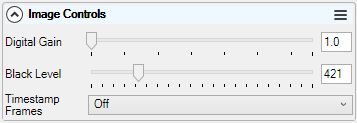
|
Image Controls |
|
|
Digital Gain |
Starlight Xpress CCD cameras do not have an analogue gain adjustment option, but the deep well depth means that a usable image can be generated even at relatively low saturation levels. Unfortunately, such images are very dark due to the signal on each pixel being low compared to the maximum signal. The digital gain option provides a way to compensate for this problem by boosting the whole image after it is read from the sensor, by a factor of up to 100x. The use of Digital Gain is particularly helpful when focussing or using the Polar Alignment tool.
|
|
Black Level |
This is a software black level adjustment. It should only be necessary to adjust this control when using the Digital Gain option (to keep the black level of the histogram down to a reasonable range).
|
SVBony Camera Controls
SharpCap supports the full range of SVBony dedicated astronomy cameras. Cameras from the SV305 upwards are supported directly. Older SVBony cameras (SV105, SV205) are supported via their Webcam drivers.
You can find driver downloads and other information about the cameras here.
There are no special controls for SVBony cameras.
ZWO Camera Controls
SharpCap supports the full range of ZWO cameras.
Drivers and further information can be found at the ZWO website.
Image Controls
|
Image Controls |
|
|
Mono Bin [Colour Cameras only] |
Only applies when binning is selected. Creates a monochrome binned image rather than a colour binned image. |
Note: ZWO cameras no longer offer a Gamma control – the ability to adjust Gamma was removed by ZWO several years ago.
Miscellaneous Controls
|
These control the auto exposure and auto gain functions of the
camera. |
|
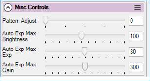
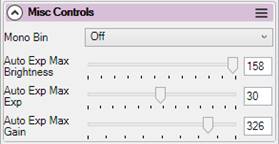
|
Miscellaneous Controls |
|
|
Auto Exp Max Brightness |
Auto Exp Max Brightness sets the target level for the maximum brightness point in the histogram in the range 50 (targets a histogram peak at about the 20% level) to 150 (targets a histogram peak at about the 60% level). |
|
Auto Exp Max Exp |
Auto Exp Max Exp is the maximum exposure (in seconds) that can be used when auto exposure is enabled. |
|
Auto Exp Max Gain |
Sets the max allowable gain in the same way. |
DirectShow Cameras
Microsoft DirectShow is an architecture for streaming media on the Microsoft Windows platform.
There are a vast number of webcams and frame grabbers on the market. In general, SharpCap should work with any of them but some cameras/grabbers have buggy drivers which may prevent them from working correctly with SharpCap. The controls available in SharpCap are determined by the driver – SharpCap just shows the controls the driver makes available. Sometimes more controls are available in the Video Capture Pin and Video Capture Filter dialogs provided by the device driver. These can be accessed using the Pin Options and Filter Options controls in the Capture Format and Area and Image Controls sections respectively. To show the respective dialog, press the Show button for that control.
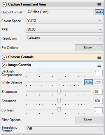
Examples of the Pin and Filter dialogs are shown below:
|
|
|
|
Video Capture Filter |
Video Capture Pin |
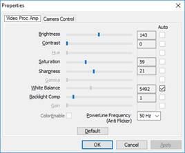
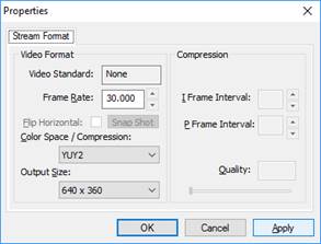
Note that the controls available in, and the design of, the Video Capture Filter and Video Capture Pin dialogs is determined by the camera driver for the camera being used, not by SharpCap.
Additionally, SharpCap allows the images being captured from a webcam to be processed by sophisticated features available to dedicated astro cam users – for instance Live Stacking and Polar Alignment are both usable with images coming from a webcam or frame grabber provided a long enough exposure can be set to start seeing details and/or stars.
Frame Grabbers
A frame grabber is an electronic device able to capture frames from an analogue video signal. The frame grabber is a USB device. The analogue video signal is commonly supplied by a day/night CCTV style security camera. This type of camera, generically called an astro video camera, is commonly based on the LN300 style CCTV body, usually with enhanced firmware or electronics which allow for internal stacking of video frames. Camera output can be to a frame grabber or an analogue screen. This arrangement is commonly used for live image display and internet video broadcasting of astronomical objects particularly in outreach type scenarios. This arrangement has proved to give satisfactory results under heavily light-polluted skies.
A typical video capture device is the EzGrabber from http://www.ezcap.tv/. [Note: there are lots of clone devices that look the same as the ezcap but may contain completely different hardware and have different drivers – sometimes these drivers have compatibility problems.]
Well known manufacturers of the astro video type cameras are Revolution Imager and Mallincam.
A typical setup comprising frame grabber and astro video camera is shown below.
|
Analogue video camera with Bluetooth adapter for accessing the camera’s internal menu. Video/power balun (left hand side) used to connect ethernet cable. |
USB2 video frame capture device. Shows in SharpCap as a USB 2861 device. |
|
From left to right – video frame grabber, balun, ethernet cable, balun, analogue video camera. |
|
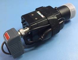
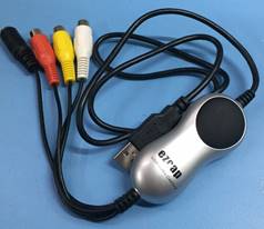
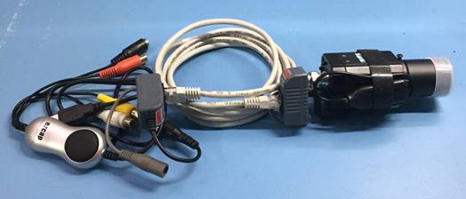
SharpCap will see this USB frame grabber as a USB 2861 (typically 28xx) device. The details of the camera connected to the frame grabbing device will not be detected by SharpCap. The camera is controlled by its own internal menu system and is usually accessed via a USB or Bluetooth connection. This type of camera typically has a maximum resolution of 720 x 576 and will be NTSC or PAL.
|
|
|
|
SharpCap view of a frame grabber |
Astro video camera internal menu |
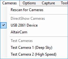
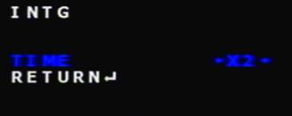
Modified Webcams
Modified webcams are those which have been electronically modified. Typical modifications are long-exposure (LX) and amp glow removal. SharpCap 3.1 and above no longer support LX modified webcams - you should use an earlier version of SharpCap (3.0 or earlier) to control these cameras. Details on their use can be found in an earlier version of this user manual.
DirectShow Controls
DirectShow cameras have a fixed set of available controls defined by Microsoft, however not all cameras will offer all these controls.
|
Format & area (Video format) · Colour space · FPS · Resolution · Frame divisor |
Camera controls · Pan · Tilt · Roll · Zoom · Exposure · Iris · Focus |
Image controls · Brightness · Contrast · Hue · Saturation · Sharpness · Gamma · Colour Enable · White Balance · Backlight Compensation · Gain |
Virtual Cameras
SharpCap can talk to a wide range of cameras directly and even more via either an ASCOM or DirectShow driver. It also has a pair of testing (simulated) cameras that can be used to try out the features of the program on cloudy nights. The Virtual Folder Monitor Camera adds another way to get images into SharpCap – it can read existing or newly added image files from a directory opening up new ways to use SharpCap. As a couple of examples:
· You have a camera that isn’t supported by SharpCap, even using a DirectShow or ASCOM driver, but you have an application that will capture frames from that camera and save them to a folder. You can use the folder monitor virtual camera to load each new frame saved to the folder into SharpCap, allowing you to access SharpCap tools like focus measurements, live stacking, etc.
· You have a series of image frames of a target captured with either SharpCap or another capture application. You can use the folder monitor virtual camera to live stack these frames in SharpCap (or repeat the live stacking with different parameters if these were frames originally saved in SharpCap).
The virtual folder monitor camera only has a limited set of controls available – it’s obviously not possible to adjust camera controls like exposure, gain or colour balance when the images are being read from saved files! The resolution and colour space values are also determined by the contents of the image files being loaded and cannot be changed.
You do have the ability to browse for the folder that contains the files you want to work with and move through the list of files in the folder either automatically (in play mode) or stepping forward/back manually in pause mode. Additionally, dark subtraction and flat frame correction can be applied and the frame rate limit can be set.
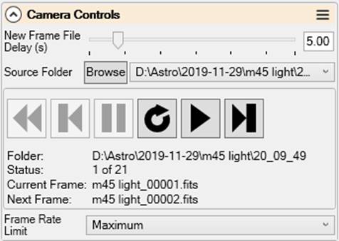
To select the folder source, press the ‘Browse’ button and either select a folder (which will process all image files in that folder) or select a single image file (PNG, TIF, FITS and JPG supported), which will process all image files of that type in the same folder. When you select a new folder:
· If the folder contains image files then the first image file of the selected file type is loaded into the camera and displayed, then the camera is paused automatically, allowing you to make any adjustments necessary or select tools such as live stacking before pressing the ‘Play’ button to begin processing the other images in the folder
· If the folder does not contain any image files then the camera will enter play mode automatically, which means that the first image will be processed and appear on screen soon after it is saved into the selected folder.
The playback controls provide a way to move through the image files present in the folder.
|
|
Rewind – go back to the first frame in the folder. |
|
|
Single Step Back – go back to the previous frame. |
|
|
Pause – cancels ‘Play’ and waits for further input. |
|
|
Replay – process the current frame again as if it had just come from a camera. |
|
|
Play – automatically process frames in turn from files already in the folder and then new files as they are added. |
|
|
Single Step Forward – move to the next available frame. |
Image files are always processed in date order (starting with the oldest first). The resolution and colour space values are selected from the first frame processed, and files that have different resolutions or colour space settings will be skipped. If SharpCap runs out of files in the folder (or if there are no image files in the folder initially) then it will wait for new image files to be added and load them when they appear.
If multiple image files are present in a folder and the ‘Play’ function is selected then they will be rapidly displayed in turn with no pause between images unless
· The frame rate limit control is set to limit the rate at which frames are displayed or
· Live Stacking is selected, in which case a new frame will be loaded only after the previous frame has completed any live stacking calculations, ensuring that no frames will be skipped by the live stacking.
Under some circumstances, errors may occur if SharpCap tries to access a newly created file immediately after it is placed into a folder (for instance if certain Antivirus software scans the file after it is created). If you see errors with SharpCap failing to read newly added files, you can increase the New Frame File Delay control to add an additional pause before SharpCap tries to process a newly added file.
![]()
The Virtual Folder Monitor Camera is a SharpCap Pro feature.
Test Cameras
The Test Cameras are useful to experiment with and understand settings and their effect. Much of the material in this manual has been derived from the Test Cameras. Hence this document can be used as a learning aid without having a telescope or camera attached to the PC/laptop or when the sky is cloudy. The use of a suitable lens (which can be purchased for a few pounds) will allow astro cameras to be tested without waiting for clear skies.
Test Camera 1 (Deep Sky)
See Camera Controls for a description of generic camera/image/display controls.
This camera has a collection of Testing Controls that allow various features of SharpCap to be tested without the need for clear skies.
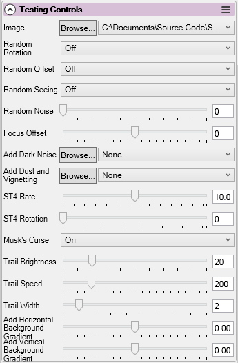
· Image – click the Browse button to load a PNG file stored in the SampleFiles folder. Other user created PNG, JPG or FITS files can be stored here for access via the test camera.
· Random Rotation – applies a random small rotation to each frame shown in the capture display area. On/Off, default = Off.
· Random Offset – applies a random offset effect to the image shown in the capture display area. On/Off, default = Off.
· Random Seeing – applies a random seeing effect to the image shown in the capture display area. The seeing effect is a blurring of the image. On/Off, default = Off.
· Random Noise – applies a random noise effect to the image shown in the capture display area. Default = 10, range 0..50.
· Focus Offset – available if no ASCOM focuser is selected. Range is -1000 to 1000. when set to non-zero, the image will be blurred to an amount that increases as the value moves away from zero.
· Add Dark Noise – adds another image to the sample image as simulated dark noise. This allows dark subtraction to be tested. The image used for dark noise can be changed by pressing Browse and must be the same size as the main image.
· Add dust and Vignetting – applies dust spots and vignetting from a flat frame to the sample image, allowing flat frame correction to be tested. The image used for this can be changed by pressing Browse and must be the same size as the main image.
· ST4 Rate and Rotation – simulates the effect of an on-camera ST4 guiding interface by moving the image in response to guiding commands. Can be used to test feature tracking.
· Musk’s Curse – add fake satellite trails to the image, the details of which can be controlled by the Trail Brightness, Trail Speed and Trail Width controls. This can be used to test the satellite trail removal feature.
· Add Horizontal/Vertical Background Gradient – adds a background to the image with a gradient in the chosen direction – these controls can be used to test the background subtraction features.
Test Camera 2 (High Speed)
See Camera Controls for a description of generic camera/image/display controls.
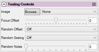
· Image – allows the image to be displayed to be chosen by pressing the Browse button or selecting from available previously used images in the dropdown. If a still image is chosen then the image will be repeated by the camera. Additionally, video files in SER format can be selected, in which case the camera will play the video file from beginning to end repeatedly.
· Focus Offset – simulate focuser movement and can be used in Focus Score > Graph. Default = 0, range -1000..+1000. Note that this Focus Offset control is only available if the selected focuser in the Hardware Settings is set to None.
· Random Offset – applies a random offset effect to the image shown in the capture display area. On/Off, default = Off.
· Random Seeing – applies a random seeing effect to the image shown in the capture display area. The seeing effect is a blurring of the image. On/Off, default = Off.
· Random Noise – applies a random noise effect to the image shown in the capture display area. Default = 10, range 0..50.
Frame rates and dropped frames
For imaging solar system targets, it’s often important to capture many frames in a short period of time, so achieving a high frame rate can be important. SharpCap shows the frame rate in the status bar along with information on how many frames have been captured by the camera so far and how many frames have been ‘dropped’.
![]()
An understanding of how dropped frames can come about and of which camera controls and other factors affect frame rate can help you get the best results out of your camera.
What affects Frame Rate?
There are three main limits on the frame rate SharpCap can achieve when receiving frames from a camera. The actual frame rate achieved will be controlled by which of the three gives the lower value.
1) The exposure in use – with an exposure of 0.1s (100ms), no more than 10fps can be achieved. Reduce the exposure to 0.01s (10ms) and the camera may be able to achieve up to 100fps.
2) The maximum frame rate achievable by the camera sensor – this may be documented by the camera manufacturer, and may increase when the camera is used in ROI mode.
3) The time taken to transfer a frame from the camera to the computer – if it takes 50ms to transfer the data then no more than 20fps are possible.
The first limit is determined entirely by the exposure time set, but the other two are more complicated. Things that may improve the frame rate for either of the last two limits include
· For USB3 cameras use a USB3 cable and a USB3 port on the computer to get maximum data transfer rate
· Use an ROI to reduce the amount of data in each frame.
· Reduce ROI height as for many cameras it has more effect on maximum frame rate than ROI width does
· Turn up any USB Speed or Turbo USB settings to try to increase data transfer rate (for QHY cameras, turn down USB Traffic).
· Capture in 8 bit modes (RAW8, MONO8) rather than high bit depth modes (RAW16, MONO16, etc) to reduce the amount of data in each frame.
Frame Rate when capturing images
When you are capturing images and saving them to file (rather than just viewing them on screen). The frame rate may be further reduced as an extra limit is introduced
4) How fast can SharpCap save images from the camera to file
This rate can vary significantly depending on:
· What format SharpCap is saving to (video formats like SER and AVI are much faster than saving each image to a separate file for PNG or FITS)
· How fast your SSD or hard disk can write data
· How full your SSD or hard disk is
If you see the frame rate drop only while capturing to file, the problem is almost certainly going to be related to the speed at which SharpCap can write images to disk or SSD. The frame rate may not drop immediately when you start capturing as SharpCap can use memory to store a number of frames waiting to be written to file, but this memory storage may fill up, after which the frame rate will drop.
Note that while SSDs are generally fast when writing data, some models have a limited amount of space set aside for ‘fast’ writing. If you fill this space by capturing large amounts of video data quickly then the write speed may drop dramatically. The SSD itself will then slowly move the newly written data to slower storage areas over time (taking from minutes to hours), releasing the fast write area for another use.
What are dropped frames?
SharpCap shows a dropped frame count to represent frames of image data that have in some way been lost or discarded. The reasons that could cause a dropped frame can include
· The frame data is lost or corrupted when being transferred from the camera to the computer
· The camera does not provide an image when one is expected
· SharpCap is applying image processing to the frames (dark subtraction, background removal, flat correction, satellite trail removal, etc) and the next frame arrives before the processing for the previous frame is finished
· SharpCap has run out of memory to store frame images waiting to be written to disk
· The frame has been rejected by some filtering criteria in SharpCap (i.e. the Seeing Filtered Capture in the Seeing Monitor).
More details on which of these might be causing dropped frames in cases where it is not obvious can be found by checking the SharpCap log and looking for lines mentioning ‘Dropped Frames’.