Telescope Hardware Control
SharpCap can control a wide variety of computer connected astronomical hardware - focusers, filter wheels, GOTO mounts, rotators and switch devices. Most devices need to be accessed via their ASCOM driver. You will need to install the ASCOM Platform, an appropriate ASCOM driver (probably supplied by the device manufacturer) and configure SharpCap to use your device. See the Hardware Settings for more details.
Once the correct drivers are installed and configured, you will see your devices listed in the Scope Controls section of the Camera Control panel:
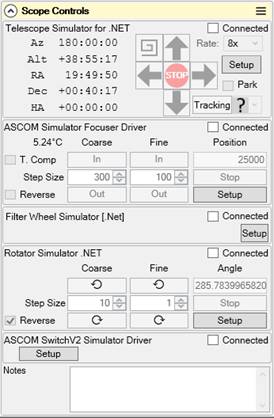
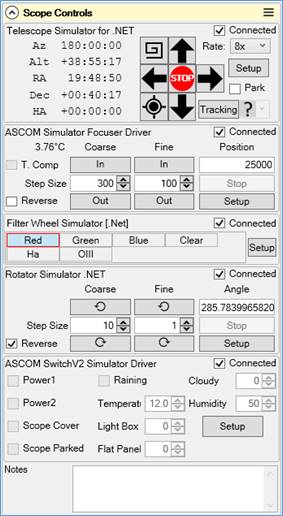
Depending on the choices you have made in the Hardware Settings, the devices may start in the disconnected state (as shown on the left). If the devices are disconnected then simply check each Connected checkbox to connect that device and make its functionality available. The Connect All Hardware button in the toolbar can also be used to quickly connect (or disconnect) all selected hardware.
GOTO Mount Control
SharpCap can connect to and control most ASCOM mounts, although the amount of functionality will depend on the capabilities of the ASCOM driver (unfortunately, if the mount does not support the ASCOM MoveAxis functionality SharpCap will offer limited functionality).
If you do not have a GOTO mount that you can connect to your computer, you may still be able to gain limited mount control via SharpCap if
· Your camera and mount both have ST4 (guiding) ports
· SharpCap supports ST4 control for your camera (Altair, PlayerOne, QHY, SVBony and ZWO cameras)
· You connect the camera and mount ST4 ports using an ST4 cable
· You select ‘On Camera ST4’ for the mount in the SharpCap Hardware Settings.
This will give you the ability to nudge the mount at the guiding rate using the direction buttons and also use Dither only Guiding.
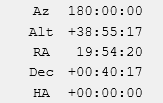
Co-ordinate Readout
On the left-hand side of the control, the current Azimuth, Altitude, Right Ascension, Declination and Local Hour Angle are shown – these are updated from the mount on a regular basis, so should update if the mount is moved using another application such as a planetarium program.
The Local Hour Angle will range from -12:00:00 (when the mount is pointing just east of due north), through to 00:00:00 (when the mount is at the meridian) and then up to +12:00:00 (approaching due north from the west). A negative Local Hour Angle means that your mount is heading towards the meridian and (for equatorial mounts) may need to flip orientation to continue imaging past the meridian. For instance a Local Hour Angle of -00:25:00 means that your mount will reach the meridian in 25 minutes.
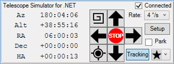
Movement Buttons
The centre section of the control is home to the movement buttons which allow the mount to be moved from within SharpCap. The up, down, left and right buttons will move the mount in the given direction while they are pressed.
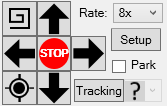
If the mount is an equatorial mount, Up/Down will move the mount in Declination and Left/Right will move the mount in RA. The mount will be moved at a speed that can be selected using the Rate drop down in the top-right of the control. This lists the movement rates that the mount makes available (this drop down shows slower movement rates in multiples of Sidereal rate – i.e. 1x, 2x, 8x – and faster rates in degrees per second). The STOP button between the direction buttons will stop any current movement of the mount but is not normally needed as movement is stopped when the direction buttons are released.
You can also move the telescope using the following keyboard shortcuts :
|
<CTRL>+J, <CTRL>+NUMPAD 4 |
Move mount left |
|
<CTRL>+L, <CTRL>+NUMPAD 6 |
Move mount right |
|
<CTRL>+I, <CTRL>+NUMPAD 2 |
Move mount up |
|
<CTRL>+K, <CTRL>+NUMPAD 8 |
Move mount down |
Note that the direction that the mount moves in response to the movement buttons and keyboard shortcuts can be reversed (if necessary) by adjusting the Hardware Settings.
The Spiral Search button (top left of the button group) moves the mount in a growing square spiral around the starting point while it is held down. This is useful when trying to locate an object such as a planet that may be just out of frame. Note that like the movement buttons, the speed of movement of the Spiral Search is governed by the Rate dropdown. If the Spiral Search button is released the spiral movement will stop. Pressing it again will begin a new spiral around the current location – it will not resume the previous spiral pattern.
Plate Solving
The Plate Solve button (bottom left of
the button group, ![]() ) will perform
a plate solve on the current image, re-synchronize the mount’s
location to the plate solve result and will the GOTO the original
target co-ordinates. This button has an identical effect to using
the Plate
Solve and Resync tool from the Tools menu.
) will perform
a plate solve on the current image, re-synchronize the mount’s
location to the plate solve result and will the GOTO the original
target co-ordinates. This button has an identical effect to using
the Plate
Solve and Resync tool from the Tools menu.
This procedure has the effect of putting the target into the centre of the field of view even if it is off-centre or out of view entirely.
The Plate Solve button only becomes enabled if a compatible plate solver is installed and configured in the SharpCap settings. See Plate Solving Settings for more details. Note that when plate solving is launched from this button, it will restrict its search to sky locations within 15 degrees of the current location as reported by your ASCOM mount. This dramatically improves the speed of plate solving, but does mean that if the current mount location is highly inaccurate, plate solving will fail.
Other Controls
The Park checkbox can be used to park or un-park your mount.
Finally, the Tracking button (bottom right) can be used to turn sidereal rate tracking of the mount on or off. If tracking is turned off, stars and other objects will appear to drift across the field of view. To the right of the Tracking button is a drop down that shows (and allows you to change) the current tracking rate. You can select sidereal, solar or lunar tracking rates. The ‘?’ icon shows when the selected tracking rate is a custom rate.

As with all ASCOM hardware in SharpCap it is possible to temporarily disconnect from the device by unchecking the Connected checkbox and the ASCOM driver configuration can be shown by pressing the Setup button.
Focuser Control
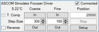
The focuser can be moved by using the In and Out buttons. Between each pair of buttons (coarse and fine) are the step size adjustment controls which allow the amount of movement per button press to be adjusted. The current position of the focuser is shown and it is also possible to directly type a new position value into this control (after typing a new value press <Tab> or <Enter> to move the focuser to the typed value). The Reverse checkbox swaps the meaning of the In and Out buttons - handy if the focuser moves in when pressing Out.
If your focuser has a temperature sensor then SharpCap will show the current temperature value below the focuser name.
If your focuser has a temperature compensation function, then the T. Comp checkbox will be available – check that box to turn on the temperature compensation function or uncheck to disable it. The temperature compensation function is provided by the ASCOM driver for the focuser, so must be configured via the ASCOM driver setup window or via other software provided by the focuser manufacturer.
Although you can use the focuser adjustment control shown above to manually change the focus position from within SharpCap, much of the power of using an electronic focuser in SharpCap comes from the integration with the focus assistance tools.
Filter Wheel Control
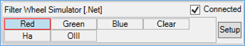
Filter Wheels are simple to control in SharpCap – the buttons show a list of filters available and all that is necessary is to select the desired filter by pressing the appropriate button. It is best to avoid trying to change the filter again while the wheel is still moving. The names of the filters shown by SharpCap can usually be configured in the ASCOM driver configuration dialog for the filter wheel.
If you use a filter wheel in SharpCap then you should adjust the Filename Settings to make sure that SharpCap puts the filter name into the filename of captured images and video files.
As with all ASCOM hardware in SharpCap it is possible to temporarily disconnect from the device by unchecking the Connected checkbox and the ASCOM driver configuration can be shown by pressing the Setup button.
As for focuser control, while it is convenient to change the filter from within SharpCap, much of the power of using an electronic filter wheel comes from the integration with other parts of SharpCap – for instance configuring the filter name to be used in file names (see Filename Settings) or using the Sequencer, Deep Sky Sequence Planner or Solar System Sequence Planner to automate an imaging session.
Filter Offsets
If you have both a filter wheel and an electronic focuser then you should, if possible, setup filter offset values for each filter inside the setup window for your filter wheel. These values represent how far the focuser needs to move when changing from one filter to another to maintain good focus.
Manual Filter Wheels
Note that SharpCap also contains the option to configure and show controls for a manually operated filter wheel. When using a manually operated wheel you can select the currently chosen filter in SharpCap, allowing the filter name to be used in custom filename templates.
Filter offsets can also be set up for a manual filter wheel, allowing you to take advantage of SharpCap automatically adjusting the focuser when changing filters. For instance, with the filter offsets setup as shown below, SharpCap would move the focuser +250 steps when moving from the clear filter to the red filter, +222 when moving from red to green, -364 when moving from green to blue, etc.
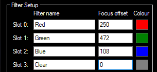
The correct filter offset values can be calculated by noting down the position of best focus for each filter in your filter when in a single test session. Pick one filter to be the ‘baseline’ and give that filter a value of zero. Assign values to all the other filters that are the difference between their best filter position and the best filter position of the baseline filter.
Note that for SharpCap to adjust the focuser when changing filters, both the focuser and the filter wheel must be connected and the option to Use Focus Offset information must have been enabled in the Hardware Settings.
Rotator Control
SharpCap can allow you to control a mechanical rotator device, allowing you to rotate the camera relative to the focuser of the telescope. Rotator devices can be used for two main purposes:
· Rotating the camera to give the best field of view for imaging a target – particularly helpful for cameras with rectangular sensors.
· Rotating the camera to counteract the field rotation that is observed when using an Alt-Az mount.
SharpCap only allows control of the rotator device for the first purpose – that of reframing the image. Using a rotator for the second purpose usually requires configuration in the rotator software so that it can monitor the mount movement and compensate accordingly.
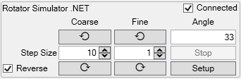
The rotator can be moved by using the Anticlockwise and Clockwise buttons. Between each pair of buttons (coarse and fine) are the step size adjustment controls which allow the amount of movement per button press to be adjusted (this is measured in degrees). The current angle of the rotator is shown and it is also possible to directly type a new angle value into this control (after typing a new value press <Tab> or <Enter> to move the rotator to the typed orientation). The Reverse checkbox swaps the meaning of the Anticlockwise and Clockwise buttons - handy if the rotator moves in the opposite direction to the expected one.
The rotator can also be controlled automatically via the Goto Image function, which can return the camera to match the position and orientation of a previous image. Additionally, various sequencer steps can use the rotator to perform tasks such as saving and restoring camera orientation after the telescope moves from one side of the meridian to the other.
Switch Device Control
The final category of hardware device that SharpCap can control is an ASCOM Switch Device. Switch devices, as their name suggests, provide the ability to switch on or off power outputs from a device and potentially switch on or off, or control, other device features. For instance, when using the Pegasus Astro Ultimate Power Box, SharpCap shows the following options:
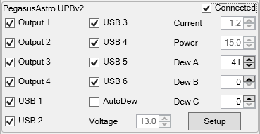
The controls here allow:
· Four separate power outputs (1 to 4) to be turned on or off
· Six separate USB ports to be enabled or disabled
· Three dew control channels (A, B and C) to be adjusted
· An Auto-dew control mode to be turned on or off
· The Voltage, Current and Power readouts to be shown
The actual controls available will vary depending on the details of the switch device being used, but the examples shown here give an idea of some of the things that might be available.
Examples of things that can be done via the controls on a ASCOM switch device include:
· Disabling then re-enabling a USB port to try to fix a problem with a glitched piece of hardware
· Turn on and off power to various devices as required to limit power usage if running on battery power
· Adjust power to dew heaters as the temperature and humidity change during an observing session
The ASCOM switch device can also be controlled via various sequencer steps as part of a larger automated imaging session.
Remote Hardware Control
SharpCap (from version 4.1) is capable of detecting and using hardware on other computers on the local network using one of the following two approaches
· ASCOM Alpaca (including ASCOM Remote)
· Indigo
SharpCap will attempt to auto-detect available remote hardware at startup. If you add new hardware, or start a remote hardware server after starting SharpCap, use the Rescan for remote hardware menu option in the File menu to get SharpCap to re-check for new hardware.
Remote Cameras
Detected remote cameras (of both ASCOM Remote and Indigo types) will appear in the Cameras menu, in the ASCOM Cameras section, typically at the bottom of the list.
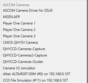
The network address of the machine on which the camera was found will appear after the camera (in the example above, 192.168.0.107) along with a device number in brackets.
These cameras can be opened and used just as other cameras can. Some things that you might need to be aware of:
· Remote cameras will always be slower than local cameras, and should only be used for slow imaging such as Deep Sky or EAA
· Remote cameras may not have all the functionality available that they would have locally.
Other Remote Hardware
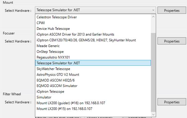
Other remote hardware (Telescope mount drivers, focusers, rotators, etc) can be found with local ASCOM devices in the Select Hardware dropdown for each device category. For instance, in the screenshot below an LX200 mount is available remotely.
Note that as for remote cameras, other remote hardware may not allow the full range of capabilities that are available when the hardware is connected to the PC on which SharpCap is running. In particular, telescope mount drivers connected via Indigo will not have access to the Move Axis commands that are required to allow the direction movement buttons in SharpCap (and other features) to work.
Using ASCOM Alpaca Hardware
ASCOM Alpaca (https://ascom-standards.org/About/Overview.htm) is a standard for remote control of astronomy hardware that is supported by SharpCap (from version 4.1). Various pieces of software can provide access to hardware via the Alpaca standard – the most obvious one is ASCOM Remote (https://github.com/ASCOMInitiative/ASCOMRemote/releases) which can be run on a Windows PC to make ASCOM devices on that PC available for use remotely.
SharpCap will automatically detect ASCOM Alpaca servers running on your local network, providing they use the default discovery port number (32227).
SharpCap cannot currently connect to servers running on computers located over the internet or servers using a non-default discovery port.
Using Indigo Hardware
Indigo (https://www.indigo-astronomy.org/) is a system for running astronomy hardware and software across multiple computers and operating systems.
SharpCap can connect to Indigo hardware via Indigo’s built in ‘ASCOM Alpaca bridge agent’. In order for SharpCap to use Indigo hardware, you must
· Enable the ASCOM Alpaca bridge agent in the Available Drivers section of the INDIGO Control Panel
· Check the Discovery Configuration setting for the Alpaca Agent has the Discovery Port set to 32227
Once these setup steps are complete and the Indigo Server is running, SharpCap should automatically detect the devices that are enabled on the Indigo Server.
NOTE: Unfortunately Indigo versions up to and including 2.0-246 contain a minor bug that prevents SharpCap from properly detecting Indigo hardware. Please update your Indigo installation to a newer version than 2.0-246 if you wish to use Indigo hardware in SharpCap.
How SharpCap handles Hardware Errors
Sooner or later, a piece of hardware that SharpCap is using could stop working properly – for instance:
· If the hardware is controlled by WIFI or Bluetooth, the wireless connection could drop out
· If the hardware is controlled by a cable, the cable could be pulled loose by mount movement
· Power to the device could be interrupted due to a low battery or a PSU problem
· The device firmware might encounter an error and stop responding
· The software managing the device on the PC (ASCOM driver, etc) may encounter an error
If one of these conditions occurs, SharpCap will most likely start to encounter errors when trying to communicate with the device.
SharpCap automatically try to deal with these errors without interrupting your imaging session in the following as described below
Errors in Status Requests
SharpCap regularly asks connected hardware devices for their current status – for instance this involves asking a Telescope Mount to report the current co-ordinates and tracking rate, or asking a focuser or rotator to report the current position.
If an error occurs while making one of these regular status update requests, SharpCap will record the problem in the log, but otherwise ignore the error. If the error clears on the next request for an update then SharpCap will continue to work with the affected device with no noticeable problems.
If, however, the error persists and occurs on every status update request, SharpCap may decide to give up on asking for status updates for that device. This will also be recorded in the SharpCap log, and will result in the status (position, etc) of the device no longer updating in the SharpCap display.
Errors in Action Requests
A more serious problem occurs when there is an error in response to SharpCap requesting the hardware device to actually do something. Examples of this include
· Requesting a telescope mount to GOTO a target or slew one or more axis
· Requesting a focuser or rotator to move to a new position
· Requesting a filter wheel to change position
SharpCap will retry these actions rather than just fail immediately if requesting an action causes an error.
The retries proceed as follows:
· After initial failure, wait 0.5s then retry
· If first retry fails, wait an additional 0.5s, attempt to disconnect then reconnect the hardware, then retry a second time
The first retry may be sufficient to deal with temporary communications glitches between the computer and the hardware device, while the second disconnect/reconnect/retry may help reset the state of the ASCOM driver or other control software into a working condition.
Note that SharpCap will not attempt to retry if the error received indicates that
· The device does not support the action being requested
· The device has been disconnected
Further details of the progress of any retries for device actions can be found in the SharpCap log.
Avoiding Hardware Errors
The simple rules to keeping hardware working reliably are:
· Avoid wireless connections (Bluetooth, WIFI, etc). Use wired connections where at all possible
· Secure wires (power and data cables) with cable ties/Velcro rather than letting them drop free
· Move the mount (and focuser/rotator if used) through the full range of positions to check that cables do not get pulled in different positions