Configuring SharpCap
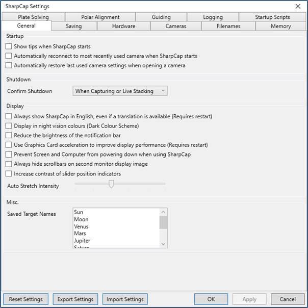
SharpCap configuration is carried out in the Settings dialog, which can be accessed from the File menu. The different settings are grouped into various tabs, each of which is discussed in the sections below.
General Settings
The General tab contains a variety of settings that are divided into four groups – Startup, Shutdown, Display, Misc.
Startup Settings
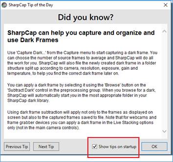
Show tips when SharpCap starts
This option is checked by default. The Tip of the Day appears when SharpCap is started but can be disabled for future start-ups here or when SharpCap starts.
Automatically connect to camera when SharpCap starts
When set, SharpCap will automatically reconnect to the last used camera at start-up. If set, this setting can be overridden by holding down the Control key when starting SharpCap, which will skip opening a camera at start-up. This setting is enabled by default.
Automatically restore last used camera settings when opening a camera
When set, SharpCap will save the current settings of each camera when you close the camera (or close SharpCap) and restore those settings the next time the camera is opened. The saved settings are stored in a hidden capture profile called ‘_autosave’ (this profile may be visible in older versions of SharpCap used on the same PC). If you do not wish to reload the previous settings then hold down the <CTRL> key while the camera is opening. This setting is checked by default.
Confirm Shutdown
By adjusting this setting, you can configure whether you are asked for confirmation when you try to close SharpCap. The options are
· Never – SharpCap will always close immediately and not ask for confirmation
· When Capturing or Live Stacking – SharpCap will ask for confirmation when actively capturing images or live stacking.
· When a camera is open – SharpCap will ask for confirmation if a camera is selected
· Always – SharpCap will always ask for confirmation of shutdown.
Note that you cannot close SharpCap while a sequence from the Sequence Planner or Sequence Editor is running – you must stop the sequence first and then close SharpCap.
Display Settings
Always show SharpCap in English, even if a translation is available
SharpCap now has partial translations to other languages (currently French, German, Japanese, Chinese). These translations will be activated automatically if one of the supported languages is set as the Windows Display Language. If you wish SharpCap to display in English even if your language has a translation, select this option.
Display in night vision colours
Selecting this option causes SharpCap to display in a dark colour scheme which is better for night-time use. You can also switch between the two colour-schemes by pressing the <F12> key. This option is unchecked by default.
|
|
|
|
Normal vision (day) colours |
Night vision colours |
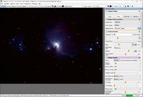
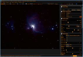
Use night vision to preserve dark adaptation of the eyes during a capture session if intending to observe visually, or if you just prefer a dark background.
Reduce the brightness of the notification bar
When this option is checked, the notification bar will be displayed with a more muted brightness, which can be helpful to keep dark adaption when using SharpCap at night. Best used with the Night Vision Colours option.
Use Graphics Card acceleration to improve display performance
When this option is checked, SharpCap will attempt to use your graphics card (GPU) to perform some of the work of displaying images and the rest of the SharpCap user interface. Sometimes, this approach can encounter problems if your graphics card is not powerful enough or the graphics card drivers have a bug. In those situations, using the graphics card acceleration may cause SharpCap to crash or hang.
Unchecking this option will stop SharpCap from using graphics card acceleration and move the work to the CPU – it may result in higher CPU usage, especially when running high resolution cameras at high frame rates.
Under some circumstances, SharpCap can detect a hang or crash caused by problems with graphics card acceleration. If that happens, SharpCap will automatically disable this option the next time the program is started. If you find this option unexpectedly disabled, this may have happened. In that case, it may be worth updating your graphics card drivers before re-enabling the option.
When updating graphics card drivers, it is usually best to go to the website of the manufacturer of the graphics card chip (i.e. Nvidia, AMD or Intel) as you will find the newest drivers there. The drivers you find on the web sites of the graphics card or computer manufacturer (i.e. Asus, Dell, MSI, Gigabyte, etc) can often be significantly older.
Prevent Screen and Computer from powering down when using SharpCap
If you enable this option, SharpCap will attempt to prevent the computer and the monitor from going to sleep while SharpCap is running.
Always hide scrollbars on second monitor display image
When selected, SharpCap will never display scrollbars on the image displayed on the second monitor in two monitor view (even if the zoom level is set so that the whole image is not visible on the second monitor). This can be useful for outreach sessions to ensure that the only thing visible on the second monitor is the camera image.
Increase contrast of slider position indicators
When using SharpCap with Night Vision Colours, or when using the normal colour scheme but using a computer in bright sunlight for solar imaging, it can sometimes be hard to see the position of the sliders used to adjust values throughout SharpCap.
By checking this box, SharpCap will add an extra highlight to the slider position indicator, making it easier to spot in difficult conditions. The higher contrast version is shown on the right below.
![]()
![]()
Auto Stretch Intensity
This setting controls how aggressive the Auto Stretch functionality in the Mini Histogram and Live Stackingis. Setting this option to a larger value with result in the Auto Stretch buttons brightening the darker regions of the image more strongly. You can adjust this option until the Auto Stretch buttons give results that suit your tastes.
Saved target names
This option is a pre-configured list of object names. Objects can be added to the list or removed from the list and the list re-ordered.
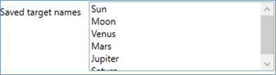
To add a new object, for example M42 or Whirlpool Galaxy, type the name anywhere into the Saved target names list. Click Apply to save the amended list. The amended list will be available the next time SharpCap is started.
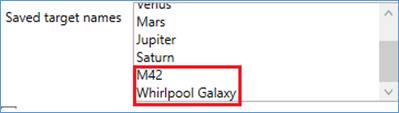
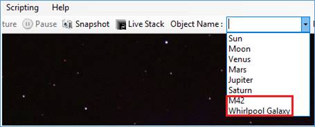
The list also appears in the Tool Bar near the
top of the screen under Object Name.
Objects added in Saved target names
will also appear in the Tool Bar dropdown
list.
Examples:
· Object Name undefined (the default) : captures saved in folder: YYYY-MM-DD\Capture
· Object Name defined : captures saved in folder: YYYY-MM-DD\Object
· Moon selected as Object Name : captures saved in folder: YYYY-MM-DD\Moon
Saving Settings
The Saving settings allow you to adjust options related to use of file formats for saved images and videos and saving capture information.
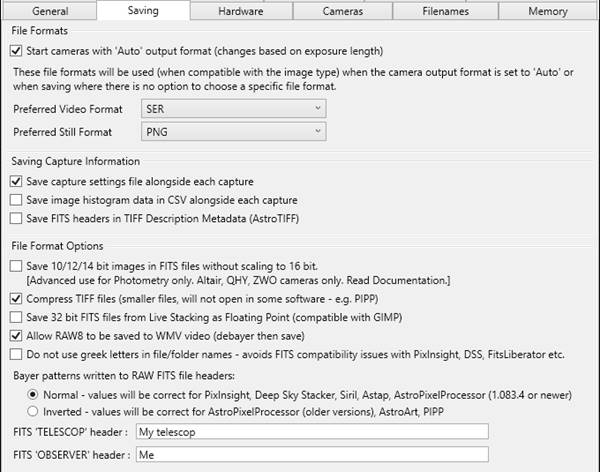
File Formats
Start cameras with ‘Auto’ output format
This option is checked by default. This option will set the Output Format control into Auto mode when a camera is opened. When the Output Format is in Auto mode a compatible video format will be chosen automatically for exposure times of less than 5s and a compatible still file format for exposure times of more than 5s. If possible, the preferred formats will be used (providing they are compatible with the camera settings in use).
Preferred File Formats
The preferred file formats specify which formats will be used when Auto Output Format is enabled and also which format will be used for saving images when there is no direct prompt for the save format. See Capture Formats Explained for information on the advantages and disadvantages of different file formats.
Preferred Video Format
The preferred video format can be chosen from SER, AVI, ADV and WMV. The default is SER. This determines the auto selected format for video captures in the camera section of the Camera Control Panel.
Preferred Still Format
The preferred still image format can be chosen from PNG, FITS, JPG and TIFF. The default is PNG. This determines the auto selected format for still images in the camera section of the Camera Control Panel.
Note that this format is also used in places where SharpCap does not prompt you for a file type when saving (for instance saving RAW frames from Live Stacking, or saving a newly created dark or flat frame).
Saving Capture Information
Save capture settings file alongside each capture
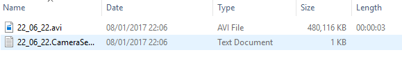
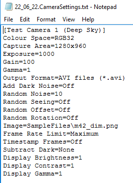
When this option is checked, SharpCap will save a text file containing all the camera settings alongside the capture file each time a new capture is started. This file is useful to check the settings used for particular images at a later date. This option is enabled by default.
|
|
|
|
22_06_22.avi & 22_06_22.CameraSettings.txt
The text file to the right contains capture settings from the Camera Control Panel – useful for reference in future observing sessions or analysis during a post-processing session.
The name of the text file reflects the time of creation.
The captured data (video or still) and the CameraSettings.txt file will have the same timestamp in their filenames. |
|
Save image histogram data in CSV alongside each capture
When this option is checked, SharpCap will save the data from the image histogram in CSV format alongside the capture file and the capture settings file. The histogram data will be taken from a frame early in the capture (usually the first captured frame).
Save FITS headers in TIFF Description Metadata (AstroTIFF)
When this option is checked, SharpCap will write equivalent data to the headers saved into a FITS file into the ‘Description’ metadata field when saving to TIFF files. This complies with the AstroTIFF metadata standard (see https://astro-tiff.sourceforge.io/). Some other Astronomy related applications may read this data automatically, or it can be viewed using a normal image metadata viewer.
File Format Options
Save 10/12/14 bit images in FITS files without stretching to 16-bit
This option is off by default and should only be enabled for special use cases where post-processing software has issues with pre-stretched images. If in doubt, do not turn this option on, and always test that you get the correct results with sample images before using this option for an imaging session.
By default, SharpCap will stretch 10,12 and 14-bit images up to use the full 16-bit range (0 to 65535) when saving those images to file (FITS, TIFF, PNG or SER formats). This is desirable because without applying this stretch the saved images would appear very dark and would all require brightening before the image could be seen properly. However, some image processing software (particularly photometry software) cannot process such pre-stretched images correctly. If you encounter this situation then you can turn this option on to make SharpCap save unstretched FITS files.
Compress TIFF files
This option is unchecked by default in new installs of SharpCap, meaning that SharpCap will not try to compress TIFF files. While using compression gives smaller file sizes, some image processing applications cannot read compressed TIFF files. Test with your image processing software if you decide to enable this option.
Save 32-bit FITS files from Live Stacking as Floating Point
By default, when saving from Live Stacking as a raw 32-bit stack, SharpCap will save to FITS format using 32-bit integer data. Some image processing software cannot correctly read 32-bit integer FITS data and may give incorrect images or an error when viewing those files. By selecting this option, SharpCap will save 32-bit data into FITS in floating point form, which gives compatibility with additional applications such as GIMP.
Allow RAW8 to be saved to WMV video
By default, SharpCap will not allow RAW camera data to be saved to compressed image or video file formats, as the compression artefacts will cause irreversible damage to the colour information encoded in the RAW image data.
When this option is selected, SharpCap will allow RAW8 images to be saved to WMV. To avoid the issues with compression destroying the colour information, SharpCap will debayer each frame to RGB colour just before saving it to WMV.
This option may be useful for all-sky cameras, where small output video size is desired, but running the camera in RAW mode to enable hot pixel removal for long exposures is also helpful.
Do not use Greek letters in file/folder names
Some image processing software (PixInsight, Deep Sky Stacker, FitsLiberator, etc) have a bug that gives errors when trying to open FITS files that have non-ASCII characters in the file or folder names. It would normally be very rare to encounter this issue, except that various stars in the SharpCap star catalog have names with Greek letters (for instance Betelgeuse is ‘α Ori’).
When this option is enabled, SharpCap will replace Greek letters such as ‘α’ in generated filenames with the word version (i.e. ‘alpha’), helping avoid triggering the bug in the various pieces of processing software.
Bayer patterns written to RAW FITS file headers
SharpCap writes the BAYERPAT and COLORTYP headers to FITS files when using a colour camera in RAW mode to inform processing software about the particular bayer pattern used by the image. Some processing software can read this information and automatically use it to correctly debayer loaded images. Unfortunately, not all processing software agrees about what the correct values for these headers are due to confusion about whether FITS image data starts at the top left or bottom left of the image.
Since there is no single ‘correct’ answer of what data to write for these headers, SharpCap has this option to allow you to choose the values that will work with your preferred processing software.
Note that the correct option for AstroPixelProcessor depends on the version in use – newer versions require Normal, while older versions require Inverted. This is because newer versions of APP read the ROWORDER keyword that SharpCap adds to the file to clarify the starting point of the FITS image data.

FITS TELESCOP and OBSERVER header values
These two fields allow the values written to the ‘TELESCOP’ and ‘OBSERVER’ headers of FITS files to be customized.
![]()
Hardware Settings
This is the
hardware screen for a default SharpCap installation. The
selected Mount, Focuser, Filter Wheel, Rotator and Switch all show
as None. 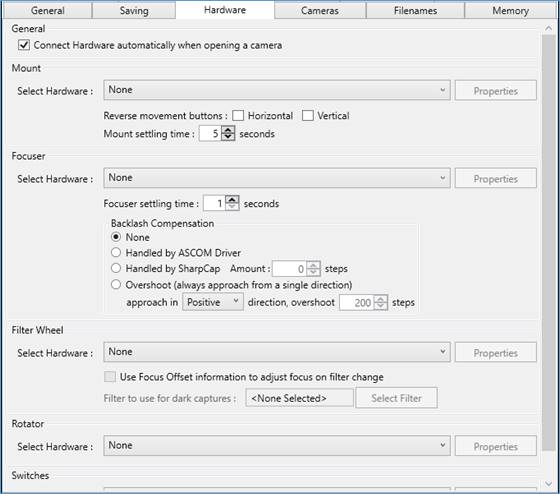
If you have a computer controlled mount, focuser, filter wheel, rotator or switch device then you can use this tab to configure SharpCap to communicate with it. In most cases, you will configure SharpCap to talk to ASCOMcompliant hardware, however there are some hardware devices that can be controlled directly via SharpCap:
· ZWO EFW Filter Wheels
· QHY Filter Wheels connected via a round plug (not USB) on the camera
· Atik and Moravian Filter Wheels built into the camera
· Mount movement via ST4 cable on selected cameras when accessed directly from SharpCap (Altair, Player One, QHY, SVBony, ZWO). Not available when the camera is accessed via an ASCOM or DirectShow driver.
· A Manual Filter Wheel. This does not actually need an electronic filter wheel, but shows in the SharpCap UI with a configurable selection of filter options. Select a filter in SharpCap when you manually chose that filter to allow SharpCap to include filter names in saved file names without an electronic filter wheel.
For SharpCap to detect ASCOM hardware you must have both the Ascom Platformand the Ascom Driver for your particular hardware installed. If you find that the drop downs are empty (or almost empty), check that the ASCOM Platform is installed and up-to-date (SharpCap may not work with older versions of the ASCOM Platform).
SharpCap can also detect and use hardware on other computers via the ASCOM Alpaca (ASCOM Remote) protocol. This can include accessing hardware on an Indigo server via Indigo’s ASCOM Alpaca Bridge Agent. See Remote Hardware Control for more information.
For each category of hardware, you can choose the device that you want to be able to use from the drop down. You can also configure that device by pressing the Properties button to the right of the drop down list. The window that shows when you press Properties is generally provided by the device’s ASCOM driver (written by the device manufacturer). In some cases this window may appear hidden behind SharpCap – check for new icons appearing in the taskbar if you do not see the device properties window appear.
Automatic Connection when opening a camera
By checking or unchecking the Connect Hardware automatically when opening a camera option you can control whether SharpCap will automatically try to establish a connection to your hardware or not. This is a matter of personal preference – if your focuser/mount/filter wheel are always available then enabling automatic connection can save the requirement to manually connect each time. If your hardware is sometimes not connected or powered off then you may get error messages when opening a camera if the automatic option is enabled – these may become annoying.
If you do not have the automatic connection option enabled then you will need to connect each device manually after opening a camera by checking the individual Connected check box for the device or by using the Connect all Hardware button in the toolbar.
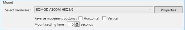
Configuring a GOTO Mount
Select your mount driver from the list in the drop down. If you have not used the mount yet (or if you have changed how it is connected to the computer), you may need to press the Properties button to configure the mount. In many cases you will need to specify a COM Port that the mount is connected to. Sometimes the COM Port number can change unexpectedly after reboots, Windows Updates or hardware changes to the PC, so this is worth checking if your mount stops working.
Along with ASCOM drivers you will also see On Camera ST4 listed as an option – if you select this option and are using a camera with a supported ST4 guiding port (Altair, Player One, QHY, SVBony, ZWO) then SharpCap will send guiding commands via the ST4 port when the mount movement buttons are used. In this case you will have limited functionality (no display of current position, etc), but will be able to nudge the mount’s location from within SharpCap as long as you have connected the ST4 port of the camera to that of the mount.
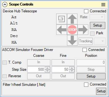
Once you have configured a mount, you will be able to use it from within the SharpCap Scope Controls area when you have a camera open.
You can also configure the following options for your mount:
· Reverse movement buttons – by checking one or both of the checkboxes you can reverse the direction the mount will move when using the movement arrow buttons in the Scope Controls area. The use of these options is a matter of personal preference.
· Mount Settling Time – this option specifies how long SharpCap will wait after the ASCOM driver reports that movement of the mount (for instance a GOTO movement) has completed before considering that the mount is settled and ready to use to take images. This value is used in SharpCap sequencer operations involving GOTO movements, Live Stacking recentering and plate solve and resync actions.
Notes on Mount Co-ordinate Systems
In order for plate solving, recentring and GOTO operations to complete correctly and accurately, it’s vital to ensure that your ASCOM mount co-ordinate system setting is setup correctly.
The direction of the Earth’s axis and the shape of its orbit vary over time. Although the changes are small and slow, over a period of years they become large enough to be noticeable. This means that the RA and Dec co-ordinates of a distant object (let’s pick the star Rigel as an example) slowly change. To deal with this problem, the co-ordinates for astronomical objects are usually listed as being for a particular date – J2000 is a common reference date, which means that the co-ordinates are those that would have been measured at the start of the year 2000. Astronomy software can convert these values for the year 2000 into the correct values for the current time (often called JNOW co-ordinates) as it knows how the Earth’s orbit changes over time.
For Rigel, the J2000 co-ordinates are : RA = 05h 14m 32s, Dec = −08° 12′ 06″
The JNOW co-ordinates (May 2021) are : RA = 05h 15m 31s Dec= −08° 10′ 44″
From this, you can see that failing to account for this can lead to a position offset of about 1 minute of RA and about 1.5 minutes of arc in Dec. If your mount co-ordinate system is set up incorrectly then this sort of error can occur in every GOTO, plate solving and re-centring operation.
SharpCap will take care of the differences between the JNOW and J2000 co-ordinates provided that your ASCOM mount driver correctly reports the co-ordinate system it uses. In theory, an ASCOM driver can report one of five co-ordinate systems: B1950, J2000, J2050, JNOW and Unknown/Other. In practice, B1950 and J2050 are unlikely to be used and are not handled. The other three options are handled as follows:
· JNOW – SharpCap assumes that the ASCOM driver accepts and reports RA/Dec co-ordinates valid for the current date. The ASCOM driver must not make internal corrections to the co-ordinates based on the date if it reports this co-ordinate system.
· Unknown/Other – SharpCap assumes that an ASCOM driver which reports Unknown/Other is really working in JNOW co-ordinates. This is the default setting for EQMOD for instance, which works in JNOW co-ordinates.
· J2000 – SharpCap assumes that an ASCOM driver which reports J2000 is telling the truth – that is that the ASCOM driver will internally convert the J2000 co-ordinates to/from JNOW as necessary, and that a GOTO to a J2000 position will point the really telescope at the targets JNOW co-ordinates. If an ASCOM driver reports J2000 and does not perform this conversion then a position error will occur in GOTO, plate solving and recentring operations.
The plate solving tools supported by SharpCap always report their results in J2000 co-ordinates. SharpCap will convert these values to JNOW co-ordinates if the mount that you are using has been identified as needing JNOW co-ordinates.
SharpCap expects all co-ordinates in object catalogues and co-ordinates entered by the user as part of GOTO movements to be in J2000 form, and will convert those co-ordinates to JNOW before sending them to the mount if required.
If you are using other applications to interact with your ASCOM mount (for instance a planetarium application such as Cartes du Ciel or SkytechX), you should ensure that you configure it to send the correct co-ordinates to the mount when performing GOTO operations. Again, if your planetarium application sends J2000 co-ordinates to a mount working in JNOW or vice-versa, the GOTO position will be slightly wrong, as will subsequent results of the Plate Solve and Resync tool.
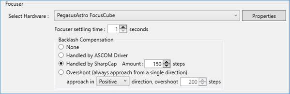
Configuring a Focuser
Select your focuser driver from the list in the drop down. If you have not used the focuser yet (or if you have changed how it is connected to the computer), you may need to press the Properties button to configure the focuser. In many cases you will need to specify a COM Port that the focuser is connected to. Sometimes the COM Port number can change unexpectedly after reboots, Windows Updates or hardware changes to the PC, so this is worth checking if your focuser stops working.
Once you have configured a focuser, you will be able to use it from within the SharpCap Scope Controls area when you have a camera open.
You can specify a Focuser Settling Time, which tells SharpCap how long it should wait after the focuser reports movement to have stopped before assuming that the camera is steady. This value is used when performing focus scans and autofocus operations to ensure that focus data is not collected while vibration from focuser movement is still present.
Focuser Backlash Handling
SharpCap can also handle backlash compensation for your focuser (your ASCOM driver may also offer this option). Setting up backlash compensation either in SharpCap or in your ASCOM driver will improve focusing reliability. There are four possible options for backlash compensation in SharpCap:
· None – No backlash compensation is in place. SharpCap may carry out additional movement steps in some focus related operations to try to limit the effects of backlash
· Handled by ASCOM Driver – select this option if you have setup backlash compensation in the ASCOM driver for your focuser. By setting this option, SharpCap knows that backlash is being dealt with by the ASCOM driver. You can also set this option if your focuser has zero backlash.
· Handled by SharpCap – select this option to have SharpCap handle the backlash compensation.
You must also set the amount of backlash that Sharpcap needs to compensate for (as measured using the procedure described below). SharpCap will adjust movement amounts when the focuser switches between moving in the positive and negative directions.
In this setting, the focuser value displayed in SharpCap may differ from that displayed by other software due to the backlash compensation.
· Overshoot – select this option to have SharpCap always approach focuser positions from a single direction, avoiding backlash problems.
When SharpCap needs to move the focuser in the opposite direction it will go past the target by the overshoot amount and then return in the selected approach direction. The overshoot amount needs to be set to a value that is larger than the amount of backlash suffered by the focuser, but there is no need for the value to be exact.
Measuring Focuser Backlash
To calculate the backlash compensation value, turn off any existing backlash compensation and measure the position of best focus twice – once with the focuser moving outwards and once with it moving inwards (with no other changes to your setup). In each measurement be sure to start the focus check well away from the point of best focus to ensure that you are not in the backlash zone when you get to best focus.
Suppose that the two positions of best focus turn out to be 21150 (moving outward) and 21020 (moving inward) – take the difference between those two values (130) and that is the amount of backlash compensation you should set. Either set this value in your ASCOM driver (and check the Handled by ASCOM Driver option) or check the Handled by SharpCap option and enter the difference between your two measurements in the Amount box.
Note that if SharpCap is handling backlash compensation then the direction of last movement and backlash state of the focuser are remembered even if you close and re-open SharpCap (as long as the focuser position is not changed by another application while SharpCap is not connect to it).
Note also that if SharpCap is handling backlash compensation then the focuser position value shown in SharpCap takes account of the backlash adjustment when moving in a negative direction – that means that the value shown in SharpCap may differ from the value shown in any UI belonging to the focuser ASCOM driver.
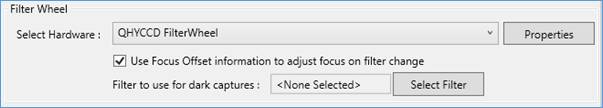
Configuring a Filter Wheel
Select your filter wheel driver from the list in the drop down. If you have not used the filter wheel yet (or if you have changed how it is connected to the computer), you may need to press the Properties button to configure the filter wheel. In many cases you will need to specify a COM Port that the filter wheel is connected to. Sometimes the COM Port number can change unexpectedly after reboots, Windows Updates or hardware changes to the PC, so this is worth checking if your filter wheel stops working.
ZWO EFW filter wheels can be detected directly by SharpCap and can be used without an ASCOM driver.
If you have a QHY filter wheel that connects to the camera via a round plug (not via USB), do not select the ASCOM driver here – SharpCap will automatically detect and activate your wheel when you open your QHY camera.
Once you have configured a filter wheel, you will be able to use it from within the SharpCap Scope Controls area when you have a camera open.
Focus Offset for Filter Changes
Some filter wheel ASCOM drivers allow you to store a focus offset value for each filter – this value indicates the amount that the focuser must be moved when selecting this filter to keep good focus (adjusting for the optical depth of the filter). If you check the Use Focus Offset information to adjust focus on filter change option then SharpCap will use this information to adjust focuser position when filter changes are made (provided you also have connected SharpCap to an ASCOM focuser).
As an example, if you move from the red filter (perhaps that has a focus offset value of 12) to the green filter (which for example has a focus offset value of 17), SharpCap will change the focuser position by +5 (17 – 12 = 5) as a result of the filter change. If you then move back to the red filter, SharpCap will move the focuser by -5. For this functionality to work correctly, it is important to have backlash compensation properly configured.
Filter for Dark Captures
If you have an opaque (dark) filter installed in your filter wheel then you can tell SharpCap the name used for this filter, which will allow SharpCap to use that filter automatically in certain operations such as:
· Capturing dark frames using the Deep Sky Sequence Planner
· Creating dark frames using the Capture Dark tool
· Creating dark flat frames using the Capture Flat tool
Configuring a Rotator
Select your Rotator driver from the list in the drop down. If you have not used the rotator yet (or if you have changed how it is connected to the computer), you may need to press the Properties button to configure the ASCOM driver for the rotator.

Once you have configured a rotator, you can use it in the SharpCap Scope Controls are when you have a camera open.
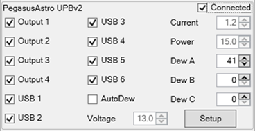
Configuring an ASCOM Switch Device
Select your Switch Device driver from the list in the drop down. If you have not used the switch device yet (or if you have changed how it is connected to the computer), you may need to press the Properties button to configure the ASCOM driver for the switch device.

Once you have configured a switch device, you can use it in the SharpCap Scope Controls are when you have a camera open.
Simulated Hardware
The ASCOM platform comes with a range of simulated hardware drivers that can be used for testing and experimentation.
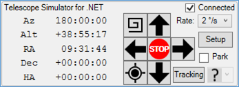
· Telescope Simulator for .NET
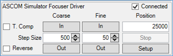
· ASCOM Simulator Focuser Driver
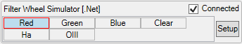
· Filter Wheel Simulator [.NET]
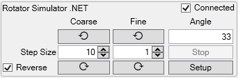
· Rotator Simulator .NET
· ASCOM Switch V2 Simulator Driver
These can be very useful for learning how to use your hardware with SharpCap in advance of an observing session. Additionally, you might find the following useful
· EQMOD ASCOM Simulator – another telescope simulator that behaves just like the EQMOD ASCOM driver for Skywatcher Telescopes
· ASCOM Sky Simulator (https://sourceforge.net/projects/sky-simulator/) – this provides a simulated camera that can be linked to the simulated focuser and mount provided by ASCOM – as you move the mount the image produced by the camera will update to reflect the part of the ‘sky’ that you are ‘observing’.
Sharing Hardware access with other Applications
There are situations in which you might want to have two or more applications access the same piece of hardware – in particular, you might want to connect SharpCap, a planetarium application like Stellarium and PHD2 Guiding to your ASCOM GOTO mount all at the same time.
Some ASCOM drivers handle this automatically and connecting 2 or more applications to the same device will just work. An example of this is the EQMOD ASCOM driver for SkyWatcher GOTO mounts.
With other ASCOM drivers, you may experience errors when you try to connect the second application to the device. These problems can usually be solved by following the guidance below.
There are typically two common causes for failure to connect a second application to an ASCOM device:
· Problems caused by running some applications in Run as Administrator mode
· Problems caused by the first application taking full control of the hardware (i.e. COM port), meaning that the second application cannot access the device
Solving Run as Administrator issues
Most problems related to Run as Administrator arise when the first application to connect to the hardware is being run As Administrator. This causes the separate application that controls the hardware to be in As Administrator mode too. Windows then prevents any non-As Administrator applications from communicating with the As Administrator ones, blocking sharing unless everything is run As Administrator.
The possible cures (in order from best to worst) are:
· Do not run any applications As Administrator. It should not be necessary for any Astronomy application. Sometimes applications need to have administrator rights to change Windows settings or for particular actions, but that should not apply to the whole application, just to those actions. Contact the application vendor for an updated version that does not need to be run As Administrator.
· Initially connect to the hardware using an application that is not running As Administrator. This should prevent problems as from that point onwards, both administrator and non-administrator applications should be able to connect.
· (If all else fails) Run all applications that need to connect to the hardware in As Administrator mode.
Solving Hardware Sharing issues
The second category of issues, hardware sharing issues, often show up as errors when trying to connect with messages such as ‘Access Denied’ or ‘Port in use’. These can usually be solved by using the ASCOM Device Hub software, which is installed as part of the ASCOM platform.
To use the ASCOM Device Hub software, adjust the settings in each piece of software so that they are set up to use the Device Hub Telescope or Device Hub Focuser as appropriate (this method does not apply for filter wheels, rotators or switch devices). In one of the applications, adjust the Properties of the Device Hub ASCOM driver to select your real hardware device (use the Choose button in the appropriate Setup window as shown below).
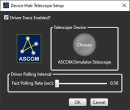
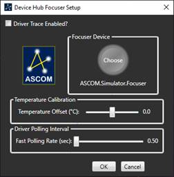
The Device Hub then acts as an intermediary – all the applications talk to the Device Hub, which passes on commands to the real hardware. The Device Hub takes care of sharing the hardware between the different applications.
Camera Settings
The camera settings contain a small number of options that control how SharpCap works with particular cameras and other related options.
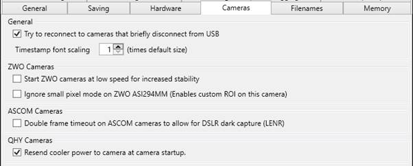
Try to reconnect to cameras that briefly disconnect from USB
Sometimes, a poor USB connection, dodgy cable, cable movement or a camera glitch can cause a USB camera to disconnect from the computer and then immediately reconnect. SharpCap can now detect this for many types of cameras, and if this option is selected, SharpCap will automatically attempt to reconnect to the camera and continue rather than report an error due to the camera being lost.
This functionality is currently supported for the following brands of camera (when used via their direct integration into SharpCap rather than via an ASCOM driver):
· Altair
· Player One
· QHY (if only one QHY camera is connected to the computer)
· SVBony
· ZWO
Timestamp Font Scaling
This setting adjusts the size of the font used to place a timestamp onto the image when the Timestamp Frames option is enabled. Larger sizes may be useful for high resolution cameras, since otherwise the text can appear very small if the images are viewed at a size to fit on screen.
ZWO Camera Settings
· Start ZWO Cameras at low speed for increased stability – ZWO cameras usually start with the Turbo USB setting set to Auto. In extreme USB conditions with long cable runs, etc, this may not give enough communication to the camera to even turn the Turbo USB to manual and reduce the value. Selecting this option will start the camera with the Turbo USB setting at minimum, which may help. Only enable if the camera is detected but fails to open successfully.
· Ignore small pixel mode on ASI294MM – The ASI294MM has options to use the sensor in 11 and 47 megapixel modes. SharpCap shows these as alternate Read Mode settings for the camera, which helps ensure that sensor analysis data for the different modes are handled correctly. However, the trade-off for this is the inability to set custom ROIs on this camera.
Enabling this option will cause SharpCap to ignore the 47 megapixel mode entirely on this camera, allowing the camera to run in 11 megapixel mode with custom ROI enabled.
ASCOM Camera Settings
· Double frame timeout on ASCOM cameras to allow for DSLR dark capture – Normally SharpCap will wait about 30 seconds beyond the set exposure value for a frame to be captured before giving up waiting and marking the frame as dropped. When certain DSLR cameras are used in long exposure mode, they take a light frame of the given exposure followed by a dark frame of the same exposure, then perform on-camera dark subtraction.
To allow time for this process to complete, enable this option, which allows SharpCap to wait up to twice the set exposure (plus an additional 30 seconds) for the frame.
QHY Camera Settings
· Resend cooler power to camera at camera startup – Some QHY cameras seem to turn off the cooler when the camera is started or the mode is changed. If this happens, enabling this option causes SharpCap to re-send the cooler power to the camera when restarting the camera, which may cure the issue. Note that SharpCap will change the cooler power setting twice (once to a different value, then back to the desired value) to force the camera to respond.
Filename Settings
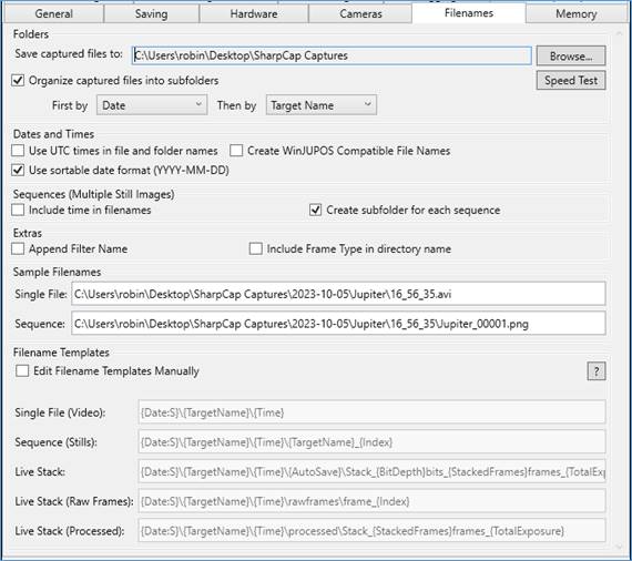
This tab allows fine control over how captured images and videos are named and organised. When adjusting the various options and settings on this page, you can see the effect of your choices by looking at the Sample Filenames that are automatically updated in response to any changes that you make.
Capture Folder Setup
Save captured files to
This allows the top-level capture folder to be selected. All captured files will be saved into this folder or subfolders created within this folder.
The capture folder in a default installation will be on the logged-in user’s desktop and is called SharpCap Captures. Note that SharpCap will check that the top-level capture folder exists and that it is not full each time SharpCap starts. If the top-level capture folder is found to be missing, full or read-only then the folder will be reset to the default of Desktop\SharpCap Captures.
The Browse… button allows other capture folders to be selected or created.
Speed Test
This button will carry out a hardware performance test of disk write speed. Running this test will discover if the camera’s capture rates are being degraded by disk write speeds.
Organise captured files into subfolders
If this is unchecked, all captures will be saved in the top-level capture folder. When checked, captured files will be saved into subfolders according to the rules selected below.
Options and combinations for folder and file names are available. Sensible defaults are offered in the initial, default installation. Examples of using the options are given below.
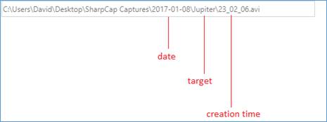
Date and then Target Name
Below is an example of a saved file organised by date then target name. File names are derived from the creation time of the capture and are in the format HH_MM_SS. Note the higher-level directory is named after the date and the inner directory named after the target.
Target Name and then Date
Below is an example of a saved file organised
by target name then date as seen in the Notification Bar
(green = success). Note the higher-level directory is named
after the target and the inner directory named after the
date.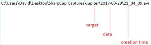
Date and Time Options
Use UTC times in files and folder names
When this option is checked, all dates and times used for filename generation will be UTC times. When it is unchecked, local times will be used.
Below is an example of a saved file using the UTC time format.
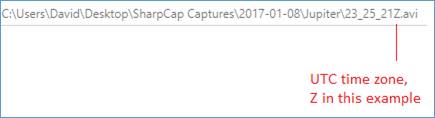
The letter designates time zone, Z = United Kingdom.
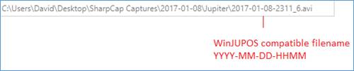
Create WinJUPOS Compatible File Names
Below is an example of a saved file using a WinJUPOS compatible name – a combination of date and time. This uses mid-point time in the capture for the WinJUPOS name. Using this option will make loading video files into WinJUPOS for de-rotation easier.
Use sortable date format (YYYY-MM-DD)
When checked, the date format YYYY-MM-DD will be used for all dates, making it easy to sort file and folder names in Windows Explorer. When unchecked, the date formatting rules appropriate to the PC’s regional settings will be used. This option is checked by default.
Other Filename Options
Sequences (Multiple Still Images)
This section provides extra options for filenames generated as part of a sequence of files (for instance when capturing frames to PNG or FITS format a file will be created for each captured frame). Do not confuse this setting with the SharpCap Sequencer or Sequence Planner. These options apply when multiple still image files are created by any means within SharpCap – for instance when pressing the Snapshot button multiple times.
· Include time in filenames – will put the current time (the time at which the frame was captured) in the filename for each captured frame.
· Create subfolder for each sequence – is enabled by default. When enabled, each new sequence of files will be stored in a separate subfolder. When disabled, many sequences may be saved in the same folder, depending on higher level folder naming choices.
Extras
· Append Filter Name – will add the name of the current filter to the file name. For this option to be effective, you must have selected a filter wheel in the Hardware Tab and ensured that it is connected correctly.
· Include Frame Type in directory name – enabling this option will create sub-directories named after the frame type being captured (e.g. Light, Dark, Flat) to help keep those files separated from each other.
Sample Filenames
This section shows sample filenames that would be generated based on your choices for file and folder naming above. The first sample shows how a filename will be generated for a single file capture (where multiple frames are saved into a single video file in AVI or SER format). The second sample shows how filenames will be generated for a sequence of files capture (where each saved frame is stored in a separate image file in a format such as PNG, FITS or TIFF).
If Filename Templates are in use then these samples show the filenames that would be generated by the Single File and Sequence templates.
Filename Templates
All capture file names in SharpCap are generated through a system of filename templates. When you adjust the various check boxes and options for file naming, SharpCap automatically generates filename templates that represent your choices. These templates are then used later to generate the actual file names. In fact, as you change the various options in for file and folder naming you can see the Filename Templates shown in the lower portion of the tab updating to represent your choices.
Sometimes you may find that you cannot obtain the file naming that you wish to achieve using the various file and folder naming options available. In this case you can choose to Edit Filename Templates Manually rather than have the templates created automatically based on your file/folder naming selections.
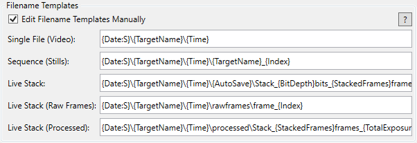
Editing the filename templates manually requires some care, but provides ultimate control over how your saved files are named. Each filename template consists of text containing one or more tags. A tag consists of a tag name surrounded by curly braces ( ‘{‘ and ‘}’ ). Tags are replaced by values when a filename is needed, so the tag ‘{Date}’ is replaced by the current date and ‘{Time}’ is replaced by the current time. The available tags are:
|
{DateTime} |
The date and time that the capture was started |
|
{Date} |
The date that the capture was started |
|
{Time} |
The time that the capture was started |
|
{TargetName} |
The name of the target object entered (or ‘Capture’ if no name entered) |
|
{Camera} |
The name of the camera being used |
|
{Filter} |
The name of the currently selected filter |
|
{Extension} |
The extension of the file (i.e. AVI or PNG). There is no need to put ‘.{Extension}’ at the end of a template. |
|
{Index} |
Sequence captures only. The index of the current frame in the sequence. |
|
{FrameDate} |
Sequence captures only. The date on which the current frame was captured |
|
{FrameTime} |
Sequence captures only. The time at which the current frame was captured |
|
{BitDepth} |
|
|
{StackedFrames} |
Live Stacking only. The total number of stacked frames so far |
|
{TotalExposure} |
Live Stacking only. The total exposure of stacked frames so far |
|
{AutoSave} |
Live Stacking only. Is the current save an autosave? |
|
{Exposure} |
Sequence captures only. The exposure of the current frame. |
|
{Gain} |
Sequence captures only. The gain of the current frame. |
|
{BlackLevel} |
Sequence captures only. The black level (offset/brightness) of the current frame. |
|
{FrameType} |
The type of frame (i.e. light/dark/flat) as selected from the toolbar dropdown. |
|
{SubExposure} |
Live stacking only. This is the exposure time of the individual frames that are being stacked. |
|
{BlackLevel} |
The camera offset/brightness/black level of the current frame. |
Some Tags can have an optional format string to change the way they are used in the filename:
|
Format |
Applies To |
Meaning |
Example |
|
:S |
Date, DateTime, FrameDate |
Use a sortable format for dates |
{DateTime:S} |
|
:Z |
Any time or date tag |
Use UTC times and dates |
{FrameTime:Z} |
|
:J |
DateTime, FrameTime |
Use WinJupos compatible format |
{DateTime:J} |
|
:U |
On any time/datetime tag |
Use UTC times, but no trailing Z is added to the time |
{FrameTime:U} |
|
:Y |
On any date/datetime tag |
Use yesterday’s date if between local midnight and local noon (i.e. dates will not change at midnight) |
{Date:Y} |
|
:2-7 |
On Index tag |
The number of digits to use for the index |
{Index:6} |
When you make changes to the filename templates you will see typical filenames updated in the Sample Filenames area described above, helping you understand how your filename templates would work.
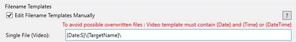
It is important to take care when customizing filename templates as you may accidentally set up templates that have undesirable results (for instance writing over previous capture files!). SharpCap attempts to detect when this might happen and will display a warning in red text explaining the problem. You cannot save or apply the new Filename Templates while there is an active warning about overwritten files.
Memory Settings
The Memory Settings tab allows you to configure how much memory SharpCap can use. In the 64-bit version of SharpCap, there are only two memory limit options that can be adjusted:
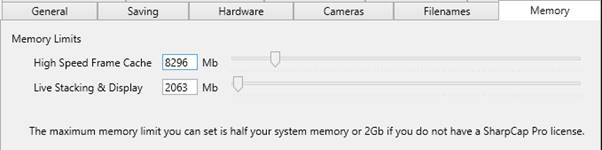
· High Speed Frame Cache – this memory is used to store frames captured from the camera before they are written to disk. If you are using a high speed USB3 camera and have a trouble with dropped frames when capturing because your disk drive or SSD cannot keep up then a large high speed frame cache will help.
· Live Stacking and Display – this memory is used to support live stacking operations and also to support the transformation and processing of images prior to display on screen. If you are Live Stacking with a high resolution camera then having a large amount of memory allocated to this category will help avoid out-of-memory errors.
By default, 1Gb of memory is allocated to each category, for a total of 2Gb. If you have a SharpCap Pro license then you can increase the amount of memory allocated to each category, up to a total of 50% of your physical memory or physical memory less 6Gb (whichever is larger). If you wish to increase the amount of memory assigned to one category, you may need to reduce the amount assigned to the other category first to keep the total at or below this limit.
If you change the settings on the Memory tab then you should restart SharpCap to ensure that they take effect correctly.
32-bit SharpCap Memory Options
On 64-bit versions of Microsoft Windows, the
32-bit version of SharpCap can also access additional memory to
improve performance and help handle the large amounts of memory
needed to perform certain functions like running Live Stacking on
very high resolution cameras. 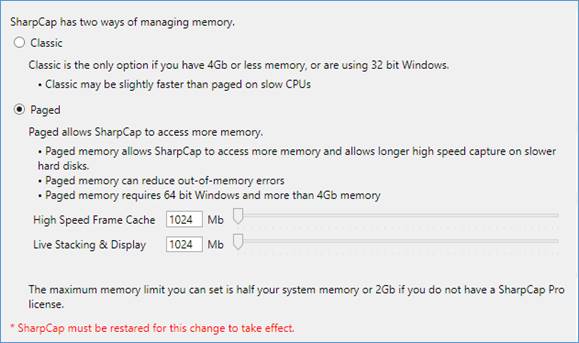
If you only have 4Gb or less of memory, or you are using a 32-bit version of Windows then your only option here is to remain on the Classic option for memory management.
If you have more than 4Gb of memory and are using a 64-bit version of Windows then Paged will be the default option for memory management (although you can switch back to Classic if you prefer).
Choosing Paged memory allows SharpCap to access more memory in total. Paged memory is divided into two categories:
· High Speed Frame Cache – this memory is used to store frames captured from the camera before they are written to disk. If you are using a high speed USB3 camera and have a trouble with dropped frames when capturing because your disk drive or SSD cannot keep up then a large high speed frame cache will help.
· Live Stacking and Display – this memory is used to support live stacking operations and also to support the transformation and processing of images prior to display on screen. If you are Live Stacking with a high resolution camera then having a large amount of memory allocated to this category will help avoid out-of-memory errors.
By default, 1Gb of memory is allocated to each category, for a total of 2Gb. If you have a SharpCap Pro license then you can increase the amount of memory allocated to each category, up to a total of 50% of your physical memory or physical memory less 6Gb (whichever is larger). If you wish to increase the amount of memory assigned to one category, you may need to reduce the amount assigned to the other category first to keep the total at or below this limit.
Plate Solving Settings
Plate Solving is a technique to work out the location in the sky of a particular image by recognizing the pattern of stars it contains against an index of known stars. If this technique is applied to an image just captured from your telescope then the calculated location will be the point in the sky that your telescope is pointing at.
Supported Plate Solving Engines and Detection
SharpCap can integrate with a number of plate-solving tools:
|
Plate Solver |
Download |
Auto Detected? |
Notes |
|
All Sky Plate Solver |
Yes |
Based on astrometry.net |
|
|
Ansvr |
Yes |
Based on astrometry.net |
|
|
Astap |
Yes |
|
|
|
Astap (CLI Version) |
No |
|
|
|
AstroTortilla |
Yes |
Based on astrometry.net |
|
|
Plate Solve 2 |
No |
Too slow for all-sky solving |
|
|
Plate Solve 3 |
via Link |
No |
|
In order to plate solve images you must first install and configure one of these tools. Remember that you must also install plate solving index files – please see documentation for the plate solving tool which will guide you on how to install index files and which index files to install.
SharpCap will automatically detect the installation of most the plate solving tools mentioned above if they have been installed into their default locations and show a summary of the detection status.
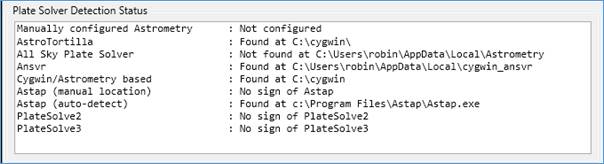
SharpCap will also check for common problems with the installation of each application (for instance missing index files) and flag any problems detected.
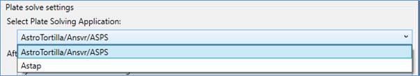
Selecting a Plate Solving Engine
You can select which plate solving engine SharpCap should use – either Astap or an installed Astrometry.net engine (Astrotortilla/ASPS/Ansvr)
If you wish to select which of Astrotortilla/ASPS/Ansvr is used (and you have more than one installed), use the Manual configuration of the location of the solve-field script as described above.
Manual Configuration of Plate Solver location
Note that if you have installed Astap, Astrotortilla, Ansvr or ASPS to a custom location, you will need to configure the location of the plate solving application by selecting the Enter Manually option and then browsing to the location of the application. For Astap, select the location of Astap.exe or Astap_cli.exe; for Astrotortilla, Ansvr or ASPS, select the location of the solve-field script.
If you have installed PlateSolve2 or PlateSolve3, you will need to tell SharpCap the path to the executable file.
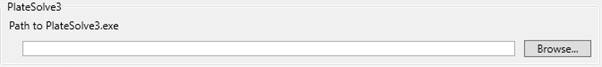
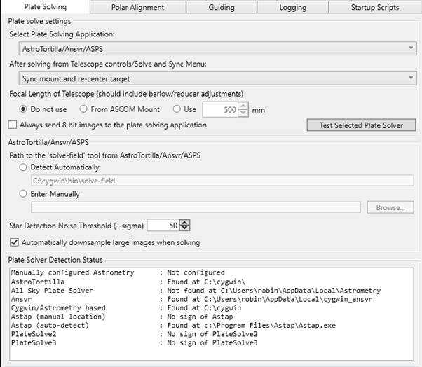
Configuring Plate Solving
You can choose the actions that SharpCap will take after plate solving and also configure the focal length of your telescope (which may speed up plate solving operations)
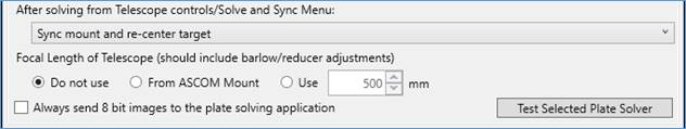
The options for actions after solving from Telescope Controls / Solve and Resync are
· Sync Mount and Re-centre target – this option will send an ASCOM Sync command to the mount based on the plate solving results and then perform a re-GOTO to the original mount co-ordinates. The net result should be that the original target is placed in view.
· Sync Mount only – this option will simply send an ASCOM Sync command to the mount based on the plate solving results.
· Offset the mounts position to centre the target – this option will perform an GOTO to a calculated position (based on the plate solving results and the original mount co-ordinates) to try to place the target in view. This option is recommended if you use a complex synchronization/pointing model in your ASCOM mount as it avoids sending Sync commands. Note that results may be inaccurate very close to the celestial poles.
· Do Nothing – this option will take no action after plate solving.
If you specify the focal length of your telescope then SharpCap will use the focal length to try to speed up plate solving operations.
The following additional option is available:
· Always send 8-bit images to the plate solving application – when selected, SharpCap will turn any high bit depth image to an 8 bit image before sending it to the plate solving application. This can help in some cases when plate solving fails and a very large number of stars are being detected.
Note: If the focal length is specified incorrectly then plate solving will almost certainly fail. If you encounter problems with unexpected failures, disable the use of focal length and re-test.
Note: Some ASCOM mounts do not allow you to set the focal length – if the ASCOM option is selected by the mount does not provide a focal length measurement then SharpCap will proceed as if the ‘Do Not Use’ option was selected.
Note: If SharpCap cannot determine the pixel size of your telescope then the focal length setting will be ignored.
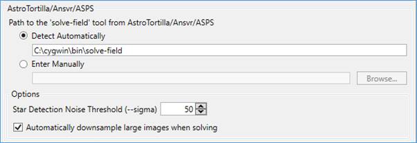
Configuring Astrotortilla/Ansvr/ASPS
Further options to configure and fine tune the Astrometry.net based plate solving engines are available as follows:
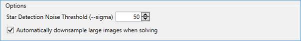
The Star Noise Detection Threshold can be configured by adjusting the numeric value of the ‘—sigma’ parameter. Higher values will tend to detect fewer stars, lower values will mean that more stars are detected. If too few stars are detected (less than 20-3) then plate solving is more likely to fail. If too many stars are detected (more than 200) then plate solving may take a very long time to complete. You may need to adjust this parameter depending on the camera/telescope combination in use.
When Automatically down sample large images when solving is enabled, images that are wider than 2000 pixels will automatically be down sampled (binned) to make them smaller before attempting to plate solve them. This option tends to dramatically improve the speed and reliability of plate solving large images with large numbers of stars visible in them.
Configuring Astap
You can specify additional options to add to the command line when running Astap.
![]()
Do not pass the following options via the additional options, as SharpCap will add them automatically to the command line : -f, -ra, -spd, -r, -log
If you pass either -fov or -z, you will override the automatic values that SharpCap selects, which may cause issues.
Testing Plate Solving
You can test the selected plate solving application by pressing the Test Selected Plate Solver button.
![]()
Pressing this button will cause SharpCap to send a known image (of stars near the north celestial pole) to the plate solving application. SharpCap will check that the plate solving succeeds and that the correct result is produced. This test checks that SharpCap has correctly detected the plate solving application and that the application and its index files are installed correctly. It also checks that any configuration (such as the sigma option or additional options for Astap) are giving reasonable results.
The Test Selected Plate Solver button DOES NOT check that the current camera is giving a suitable image for good plate solving results.
To test that the current camera settings give good results, use the Plate Solve Only or Plate Solve and Resync tools from the Tools menu. These will send an image from the camera to the configured plate solving application. The following hints will help get good plate solving results if you have issues:
· Turn off Display Stretch if you have it enabled so that you can see how many stars are visible in the unstretched image
· Set an exposure of 2 to 4 seconds and a high gain - this should make a decent number of stars appear. Set a higher exposure/gain if you still see very few stars (i.e. small field of view with a long focal length telescope and/or small camera sensor).
· Check that the plate solving index files that you have installed are suitable for the field of view of your camera. You can check the field-of-view by using the Astronomy Toolswebsite.
· Watch the notifications shown as the plate solving attempt runs. If you have failures then look out for the number of stars that are being detected by the plate solving application
· If the number of stars is below 100 and you are having problems, increase exposure and/or gain, or reduce the sigma setting if applicable
· If the number of stars is above 200 and you are having problems, reduce sigma if applicable, decrease exposure or gain, or try the Always send 8-bit images to the plate solving application option.
Polar Alignment Settings
SharpCap’s Polar Alignment routine can become more accurate and easier to use if SharpCap knows your latitude and longitude. By default, SharpCap estimates your longitude from your computer’s time zone settings and estimates your latitude to be 45 degrees North or South. This is sufficient for Polar Alignment to work, but setting your correct latitude will allow SharpCap to correct for atmospheric refraction giving a more accurate result. Setting your correct longitude will ensure that up/down/left/right movement instructions are accurate.
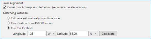
You can choose to leave the observing location as the default setting (Estimate automatically from time zone) or choose either of the two accurate location options – using the location from your ASCOM mount or specifying a location manually. If you choose an accurate location option then you can enable the option to correct for atmospheric refraction.
The location provided does not need to be perfectly accurate – latitude and longitude correct to the nearest degree are accurate enough.
Finally, you can use the ‘Geolocate’ button to find your current location automatically if you are connected to the internet. This will send your IP address to an internet server which will respond with your approximate location. This approach may not work for all internet providers and will probably not work well if you are connected to the internet via a mobile device.
Important Note: If you are not using a GOTO mount, or if your GOTO mount does not report latitude/longitude, SharpCap will use the location defined here to calculate object positions in the sky, rising and settings times, etc. Setting your location may enhance functionality in other parts of the software.
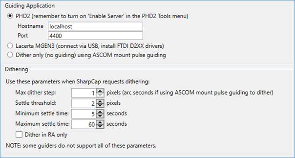
Guiding Settings
SharpCap can work with the popular freeware guiding application PHD2 and also the MGEN3 Autoguider to monitor and control guiding and dithering while live stacking or running a capture sequence using the Sequencer Tool or Sequence Planner. SharpCap can also send dithering commands to your ASCOM GOTO mount without needing a guiding application.
Using PHD2
In order to enable integration between SharpCap and PHD2, ensure the following:
· PHD2 is a recent version and running on the same computer as SharpCap
· the Enable Server menu item must be selected in PHD2
Using the MGEN3 Autoguider
In order to use your Lacerta MGEN3 autoguider, you must install the MGEN3 Windows drivers (scroll down and choose the Windows drivers from the top row of the driver table). You must also connect your MGEN3 device to your PC using a USB cable.
Using Dither Only Guiding
Dither only guiding provides a way to include dithering in your live stacking and imaging sequences without needing to actually have a guiding application/device active. Dither only guiding is considered by SharpCap to always be active (guiding), but will never send guiding corrections to your mount. Dither only guiding will however send a small, random, movement command to the mount whenever dithering is needed.
When using an ASCOM mount, Dither Only Guiding will use the Pulse Guiding functionality of ASCOM to send movement requests to the mount. This is available on most (but not all) ASCOM mounts. You may also be able to adjust the rate at which the mount moves in response to the pulse guiding requests in your ASCOM mount setup.
If you do not have a GOTO mount, or your mount does not support pulse guiding, you may still be able to use this option if
· Your camera and mount both have ST4 (guiding) ports
1. SharpCap supports ST4 control for your camera (Altair, PlayerOne, QHY, SVBony and ZWO cameras)
2. You connect the camera and mount ST4 ports using an ST4 cable
3. You select ‘On Camera ST4’ for the mount in the SharpCap Hardware Settings.
Dithering
SharpCap Pro users can also enable dithering using one of the supported guiding options while live stacking or using the Sequencer/Sequence Planner. In order to enable dithering, tick the Automatically Dither checkbox in Live Stacking or select dithering in the Sequencer/Sequence Planner. You can set options here to control details of each dither operation.
Max Dither Step – this specifies the maximum distance that any dither movement can be, measured in guide camera pixels (i.e. pixels in PHD2, not in SharpCap). Note that MGEN does not take any notice of this setting, and that if Dither Only Guiding is selected then this setting is interpreted as the size of the dither movement step in arc-seconds.
Settle Threshold – when the movement between two guide camera frames drops below this number of pixels then the dither is considered to have ‘settled’ – i.e. the mount movement is complete and images taken should no longer be blurred by movement. Only applies to PHD2 guiding.
Minimum Settle Time – a dither will not be considered to be settled until this amount of time has elapsed after the end of the movement, even if the Settle Threshold is met before this time has elapsed. Only applies to PHD2 guiding.
Maximum Settle Time – a dither will always be considered to be settled after this amount of time has elapsed, even if the settle threshold has not been met. Only applies to PHD2 guiding.
Dither in RA only – restrict dithering to the Right Ascension axis only. Only applies to PHD2 guiding.
Logging Settings
Troubleshooting
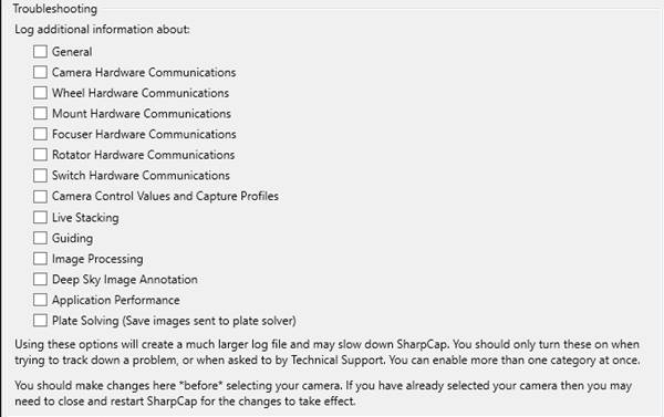
SharpCap writes a significant amount of information to its log by default, particularly if any problems occur, but sometimes extra information is required to track down an issue.
By selecting one or more of the options here, you can configure SharpCap to log additional information to help diagnose an issue. When one or more of these options are turned on, SharpCap will write significantly more information to its log. Turning these options on may result in SharpCap running more slowly or becoming less responsive due to the extra information being logged, so it is not recommended that you turn this option on unless you are trying to track down a problem or are asked to by SharpCap support.
If you turn on one or more of these options, you will be prompted to confirm whether to keep them turned on each time you start SharpCap.
The categories of additional logging that you can enable are :
· General – any information that does not fall into the categories below.
· Camera Hardware Communications – details of any communications between SharpCap and the hardware/manufacturer provided software of a camera in use.
· Wheel Hardware Communications – details of any communications between SharpCap and the ASCOM driver of a filter wheel in use.
· Mount Hardware Communications – details of any communications between SharpCap and the ASCOM driver of a mount in use.
· Focuser Hardware Communications – details of any communications between SharpCap and the ASCOM driver of a focuser in use.
· Rotator Hardware Communications – details of any communications between SharpCap and the ASCOM driver of a rotator in use
· Switch Hardware Communications – detail of any communications between SharpCap and the ASCOM driver of a switch device in use
· Camera Control Values and Capture Profiles – log information about changes to camera controls (but not other camera related information)
· Live Stacking – log additional information related to live stacking progress and errors to the main SharpCap log
· Guiding – log additional information relating to communication between SharpCap and a guiding application/device.
· Image Processing – log additional information about timings and outcome of image processing operations, including details of the number of hot/cold pixels that are being corrected
· Deep Sky Image Annotation – log additional info about object positions and related calculations when using image annotation
· Application Performance – log additional information about the times taken to process frames in SharpCap, showing the time delay at each stage as the frame passes from camera to display
· Plate Solving – log additional information about plate solving, including saving any images sent to the plate solving application. Unlike other options, this option causes information to be logged in subfolders of a PlateSolveImages folder created inside the main SharpCap Captures folder. Each subfolder will contain an image file (i.e. Image.fits or Image.png) and a log file names info.txt. The info.txt file contains full details of the plate solving application being used, the plate solving settings and parameters passed to the plate solving engine as well as the output that the plate solving engine produced.
GPS Logging
Log all QHY GPS data to file
SharpCap supports QHY cameras with built in GPS. When the GPS is activated on such cameras, the default behaviour is to store the GPS data (time, date, location) in FITS headers or in the capture settings file. However sometimes it is desirable to keep a more detailed record of the GPS information – enabling this option will create such a log file in CSV format in the root capture directory each time a GPS enabled camera is used.
This option is disabled by default and you should restart SharpCap after changing this option to be sure that it takes effect.
The format of each line of the log file is
<PC Clock Time>, <GPS Status>, <Frame Number>, <Frame Start Time from GPS>, <Frame End Time from GPS>, <Latitude>, <Longitude>, <RawLatitude>, <RawLongitude>
The RawLatitude and RawLongitude are the un-decoded values received from the camera. Contact QHY for the steps necessary to decode these values if you wish to decode them separately.
Start-up Scripts
This tab allows a list of Python scripts, to be run at SharpCap start-up, to be configured. Such scripts can be used to add additional features or customizations to SharpCap every time it is started. Use the Add, Remove, Move Up and Move Down buttons to manage the list of start-up scripts.
For example, the following Script will create a button on the toolbar that selects the first camera when pressed. The code can be created and saved by following the information in Scripting.
def selectFirstCamera():
SharpCap.SelectedCamera=SharpCap.Cameras[0]
SharpCap.AddCustomButton("Test", None, "Select the first camera",
selectFirstCamera)
Save the script somewhere (call it SelectFirstCamera.py for example), say on the desktop and configure File > SharpCap Settings > Startup Scripts accordingly.
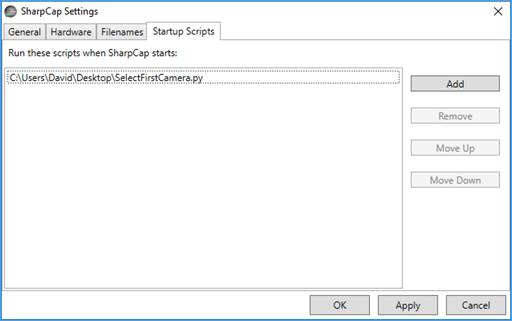
Deselect the camera, restart SharpCap and the button Test should be added to the right-hand end of the Tool Bar, together with the camera having been selected.
![]()
This technique is good to use for the start-up script as it allows creation of custom toolbar buttons and have them load every time SharpCap is started.
The Test button can be removed via File > SharpCap Settings > Startup Scripts, highlighting the script SelectFirstCamera.py, selecting Remove and restarting SharpCap.
Saving, Restoring and Resetting the SharpCap Settings
In the bottom left of the Settings window you will find three buttons that allow you to reset, export and import SharpCap settings. These allow you to easily set SharpCap back to defaults or to copy SharpCap settings from one computer to another one.
![]()
Reset Settings
Use the Reset Settings button to reset some or all of SharpCap’s settings. You will see a window allowing you to choose which data should be reset.
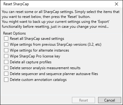
You need to choose one or more of the options before pressing the Reset button.
· Reset all SharpCap saved settings – this will reset all options in the various pages of the SharpCap Settings Window, as well as various options found in other parts of the product.
· Wipe settings from previous SharpCap Versions – this will clear all settings from older SharpCap versions. When used in SharpCap 4.1, it will clear all settings from 4.0, 3.2, 3.1, etc. It is often a good idea to use this with Reset all SharpCap saved settings, as otherwise once the current settings are reset, the next time you run SharpCap it will think you have just upgraded from 4.0 and copy the settings used by 4.0 to 4.1.
· Wipe settings for alternate instances – if you have used the /instance command line parameter to set up alternate configurations for SharpCap, choosing this option will wipe that data.
· Wipe SharpCap Pro license key – will delete the current SharpCap Pro license key
· Delete all capture profiles – delete any saved capture profiles including the information used to auto-restore camera settings when a camera is re-opened.
· Delete sensor analysis measurement results – wipes any sensor analysis data files that you have created by running the Sensor Analysis tool on your cameras
· Delete sequencer and sequence planner autosave files – deletes the files that are used to auto-restore sequence planner and sequencer configuration.
· Delete custom annotation catalogs – deletes any custom annotation catalogs that you have added.
Some of these items may be disabled (greyed out and not selectable) if there is no data of that type that could be deleted.
When you have selected the data you would like to delete, press the Reset button, which will cause a confirmation message to be shown.
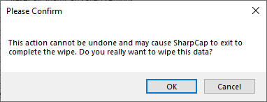
If you have selected certain items of data (for instance all SharpCap saved settings or all Capture Profiles), SharpCap will exit after the wipe has been completed. Re-run SharpCap to start using the re-set settings.
Note that this functionality may not operate correctly if two or more copies of SharpCap are running when it is used.
Export Settings
Use the Export Settings button to save all SharpCap settings from the current computer to a file. You will need to choose a folder location and name for the file – for instance Desktop\SavedSettings.SharpCapSettings.zip (SharpCap will add the .SharpCapSettings.zip part). You can then transfer this file to another computer and import it using the Import Settings button.
The following data is saved when exporting settings:
· Settings shown in the Settings Window and other parts of the software
· Capture Profiles
· Sensor data created using the Sensor Analysis tool
· Custom annotation catalogs
· Autosave information for the sequencer and sequencer planner tools
The following data is not included:
· The SharpCap Pro license – this must be transferred separately
· Settings from older SharpCap versions
· Settings from alternate SharpCap configurations created using the /instance command line parameter (but you can export each of those separately if you wish)
When the save process is completed, SharpCap will confirm that it was successful and launch a Windows Explorer window to show the newly created exported settings file.
Since the saved data file is just a .zip file, you can open it and look at the data inside if you wish.
Import Settings
If you have previously exported your settings, then you can use the Import Settings button to import them – either on a different PC, or on the same PC to reset the settings back to previous values.
When you have pressed the Import Settings button, you will need to locate the settings file (*.SharpCapSettings.zip) to load. Once the file is selected, SharpCap will prompt you for confirmation of the import.
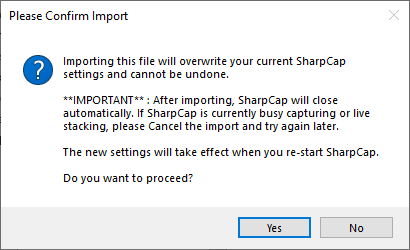
Importing settings will overwrite:
· Settings shown in the Settings Window and other parts of the software
· Capture Profiles
· Sensor data created using the Sensor Analysis tool
· Custom annotation catalogs
· Autosave information for the sequencer and sequencer planner tools
SharpCap will close when the import is complete and you will need to re-run SharpCap to use the new settings.